Toyota Sequoia (2005). Manual — part 301
F19196
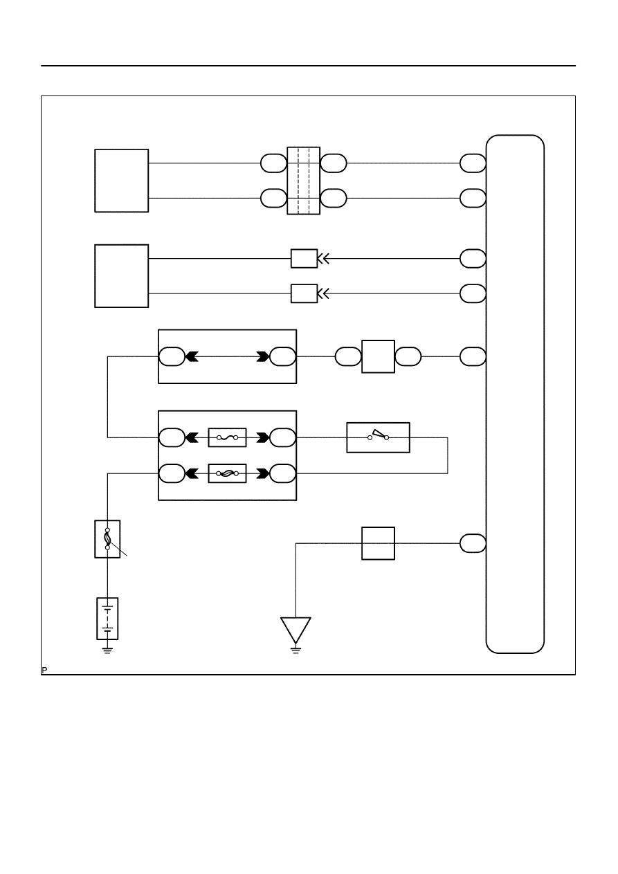
E5
ECM
CANL
CANH
34
33
W
L
2
J53
1
J53
2
J55
1
J55
J/C
W
R
16
T5
14
T5
ENG–
ENG+
VSC+
VSC–
7
T5
11
T5
L
W
W
L
7
IL2
6
IL2
2
6
S1 ABS & VSC Actuator
(Skid Control ECU)
Translate
ECU
IG1
1
T5
B–R
J37
J37
J/C
Sub J/B No.3
8
3C
8
3A
B–R
B–R
B–Y
W–L
I18
Ignition SW
W
Instrument Panel J/B
4
1F
1
1L
4
1C
6
1C
ECU–IG
AM1
AM1
IG1
ALT
Battery
GND
40
T5
J43
J/C
O
A
A
O
IG
1
2
CANH
CANL
A
A
8
5
B
F10
Fusible Link
Block
(*1)
(*1)
(*2)
(*2)
(*1) Vehicle CAN Circuit
(*2) CAN1 Circuit
(*1)
(*1)
(*2)
(*2)
–
DIAGNOSTICS
ABS WITH EBD & BA & TRAC & VSC SYSTEM
DI–999
1193
WIRING DIAGRAM
F19152
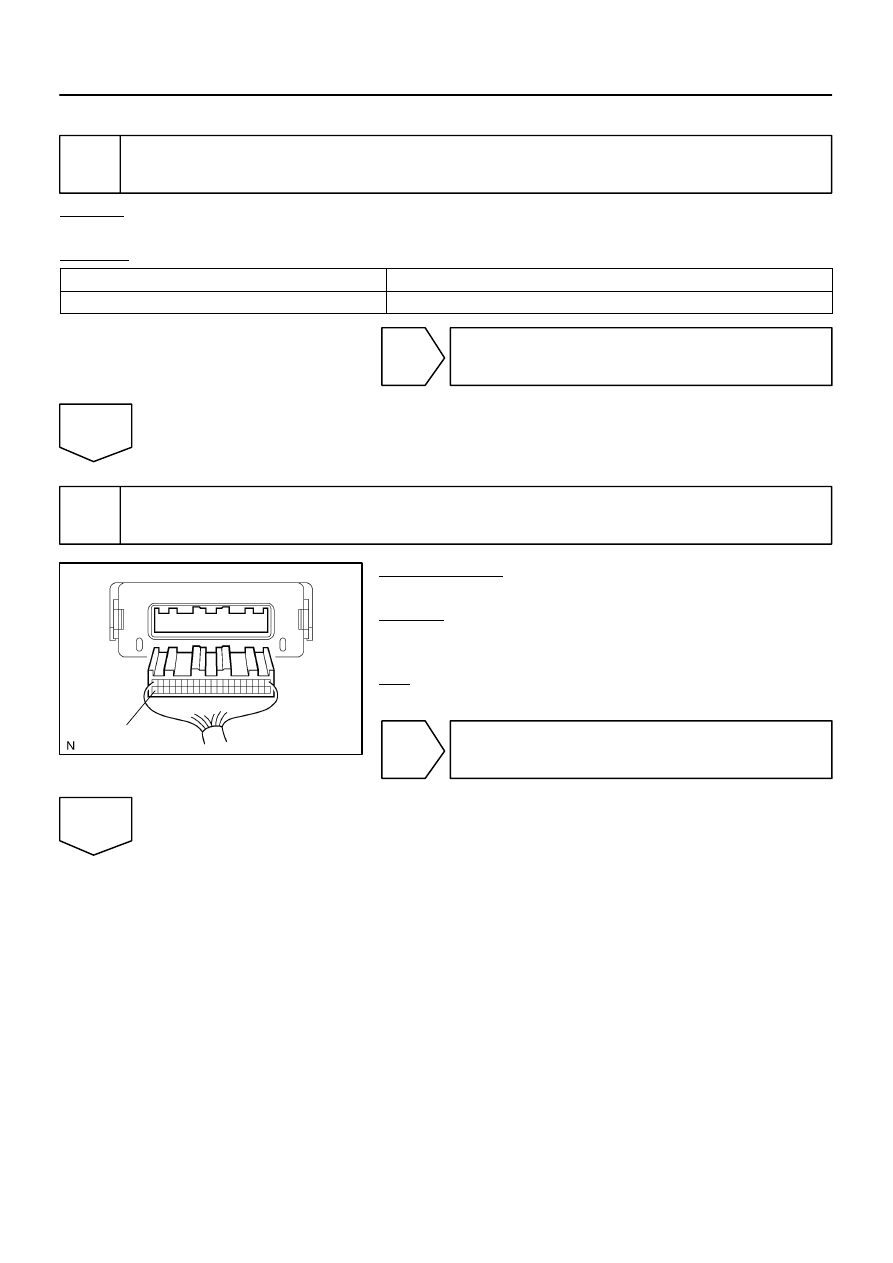
Translate ECU
GND
DI–1000
–
DIAGNOSTICS
ABS WITH EBD & BA & TRAC & VSC SYSTEM
1194
INSPECTION PROCEDURE
1
Check the DTC of the VSC (See page
CHECK:
Check skid control ECU DTC.
RESULT:
DTC is not output
A
DTC (C1203/53) is output
B
B
Repair circuit indicated by the output code
(See page
).
A
2
Check for open circuit in harness and connector between GND terminal of the
translate ECU and body ground.
PREPARATION:
Disconnect the translate ECU connector.
CHECK:
Measure the resistance between the GND terminal and body
ground.
OK:
Continuity
NG
Repair or replace harness or connector (Trans-
late ECU GND circuit).
OK
–
DIAGNOSTICS
ABS WITH EBD & BA & TRAC & VSC SYSTEM
DI–1001
1195
3
Replace the translate ECU and check if the trouble occurs again.
PREPARATION:
(a)
Clear the translate DTC (See page
).
(b)
Turn the ignition switch OFF.
CHECK:
Turn the ignition switch to the ON position, and check if the same DTC is stored in the memory.
PREPARATION:
DTC 53 is not output
A
DTC 53 is output
B
B
Replace skid control ECU
(See page
NOTICE:
When replacing the skid control ECU, perform zero point
calibration (See page
A
END
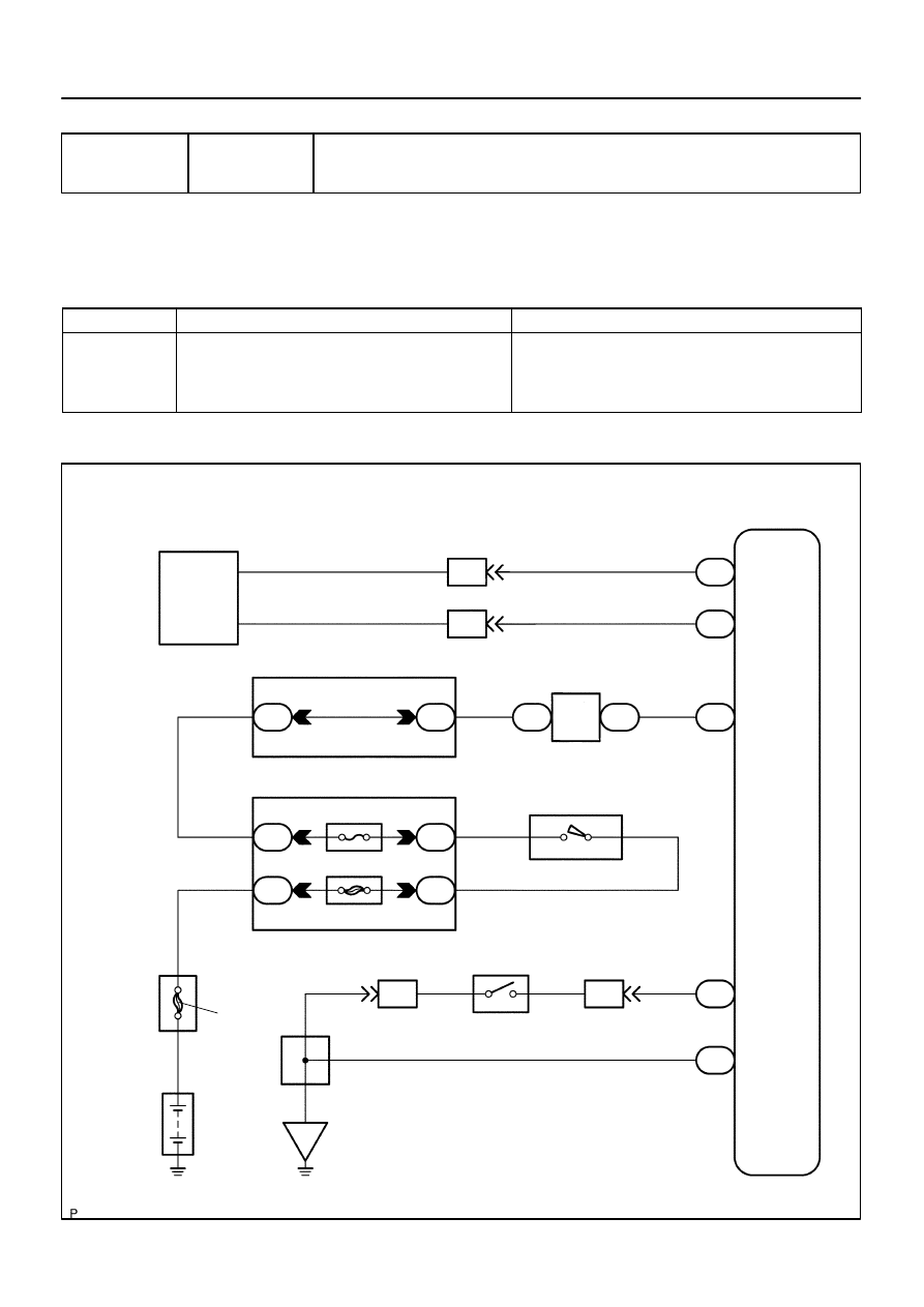
F19197
S1 ABS & VSC Actuator
(Skid Control ECU)
Translate
ECU
CANH
CANL
6
2
L
W
L
W
7
IL2
6
IL2
7
T5
11
T5
VSC+
VSC–
IG1
1
T5
B–R
J37
J37
J/C
B–R
B–R
8
3C
8
3A
I18
Ignition SW
4
1F
4
1C
1L
6
1C
ECU–IG
AM1
AM1
IG1
B–Y
2
W–L
W
ALT
Battery
24
T5
40
T5
LVL2
GND
23
IA1
9
IA5
Y–L
Y–L
W–B
O
A
O
A
A
B1
Brake Fluid
Level Warning SW
J43
J/C
IG
1
Sub J/B No.3
Instrument Panel J/B
8
5
F10
Fusible Link Block
B
1
1
2
2
A
A
1
(*) CAN1 Circuit
(*)
(*)
(*)
(*)
DI–1002
–
DIAGNOSTICS
ABS WITH EBD & BA & TRAC & VSC SYSTEM
1196
DTC
58
Malfunction of Brake Fluid Level Warning
Switch
CIRCUIT DESCRIPTION
The brake fluid level warning switch sends the appropriate signal to the translate ECU.
This signal indicates a drop in brake fluid level.
DTC No.
DTC Detecting Condition
Trouble Area
58
Brake fluid level warning switch connector is disconnected
for 1 sec. or more.
Brake fluid level warning switch is ON for 30 sec. or more.
Brake fluid level warning switch circuit
Brake fluid level warning switch
Brake fluid reservoir level
Translate ECU
WIRING DIAGRAM
DIDMI–01
Нет комментариевНе стесняйтесь поделиться с нами вашим ценным мнением.
Текст