Toyota Sequoia (2005). Manual — part 91
B17394
Fuel
Compensation
Amount
1.35
1.0
0.65
+35 (%):
Lean Malfunction Threshold
–35 (%):
Rich Malfunction Threshold
P0171, P0174:
P0172, P0175:
–
DIAGNOSTICS
ENGINE
DI–167
361
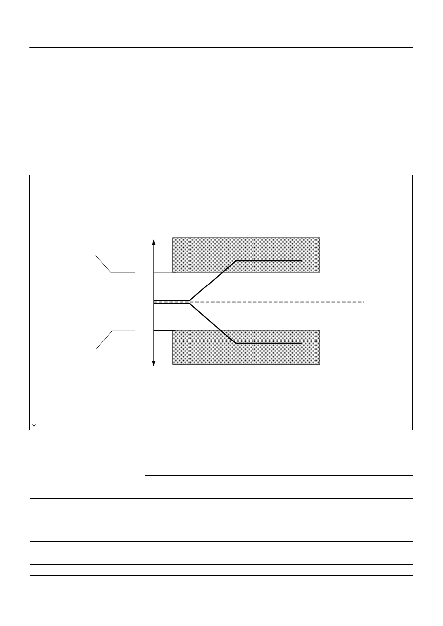
MONITOR DESCRIPTION
Under closed–loop fuel control, fuel injection volumes that deviate from those estimated by the ECM cause
changes in the long–term fuel trim compensation value. The long–term fuel trim is adjusted when there are
persistent deviations in the short–term fuel trim values. Deviations from the ECM’s estimated fuel injection
volumes also affect the average fuel trim learning value, which is a combination of the average short–term
fuel trim (fuel feedback compensation value) and the average long–term fuel trim (learning value of the air–
fuel ratio). If the average fuel trim learning value exceeds the malfunction thresholds, the ECM interprets
this a fault in the fuel system and sets a DTC.
Example:
The average fuel trim leaning value is more than +35 % or less than –35 %, the ECM interprets this as a fuel
system malfunction.
MONITOR STRATEGY
P0171
Fuel system lean (Bank 1)
R l t d DTC
P0172
Fuel system rich (Bank 1)
Related DTCs
P0174
Fuel system lean (Bank 2)
P0175
Fuel system rich (Bank 2)
Main sensors/components
Front oxygen sensor
Required sensors/components
Related sensors/components
Engine coolant temperature sensor, Mass air flow
meter, Crankshaft position sensor
Frequency of operation
Continuous
Duration
10 sec.
MIL operation
2 driving cycles
Sequence of operation
None

DI–168
–
DIAGNOSTICS
ENGINE
362
TYPICAL ENABLING CONDITIONS
It
Specification
Item
Minimum
Maximum
The monitor will run whenever these
DTCs are not present
See page
Battery voltage
11 V
–
Fuel system status
Closed–loop
Throttle position learning
Completed
Either of the following conditions is met:
Condition 1 or 2
1. Engine RPM
–
1,000 rpm
2. Intake air amount per revolution
0.26 g/sec.
–
Catalyst monitor
No executed
TYPICAL MALFUNCTION THRESHOLDS
Detection Criteria
Threshold
Purge–cut
Executing
Either of the following conditions is met
Condition 1 or 2
1. Average between short–term fuel trim and long–term fuel
trim
35% or more (varies with ECT)
2. Average between short–term fuel trim and long–term fuel
trim
–35% or less (varies with ECT)
WIRING DIAGRAM
Refer to DTC P2195 on page
.
INSPECTION PROCEDURE
HINT:
Hand–held tester only:
Malfunctioning areas can be identified by performing the A/F CONTROL function provided in the ACTIVE
TEST. The A/F CONTROL function can help to determine whether the Air–Fuel Ratio (A/F) sensor, Heated
Oxygen (HO2) sensor and other potential trouble areas are malfunctioning.
The following instructions describe how to conduct the A/F CONTROL operation using a hand–held tester.
(1)
Connect a hand–held tester to the DLC3.
(2)
Start the engine and turn the tester ON.
(3)
Warm up the engine at an engine speed of 2,500 rpm for approximately 90 seconds.
(4)
On the tester, select the following menu items: DIAGNOSIS / ENHANCED OBD II / ACTIVE
TEST / A/F CONTROL.
(5)
Perform the A/F CONTROL operation with the engine in an idling condition (press the RIGHT
or LEFT button to change the fuel injection volume).
(6)
Monitor the voltage outputs of the A/F and HO2 sensors (AFS B1S1 (AFS B2S1) and OS2 B1S2
(O2S B2S2)) displayed on the tester.
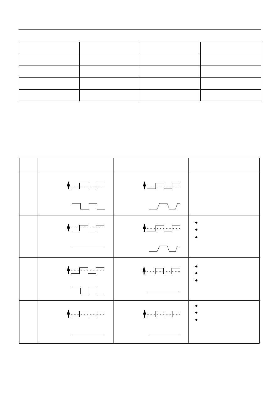
HINT:
The A/F CONTROL operation lowers the fuel injection volume by 12.5 % or increases the injection
volume by 25 %.
Each sensor reacts in accordance with increases and decreases in the fuel injection volume.
+25 %
–12.5 %
More than 3.35 V
Less than 3.0 V
1
A/F Sensor (Sensor 1)
Output Voltage
Injection volume
Output voltage
HO2 Sensor (Sensor 2)
Output Voltage
Main Suspected
Trouble Areas
OK
+25 %
–12.5 %
More than 3.35 V
Less than 3.0V
Injection volume
Output voltage
+25 %
–12.5 %
More than 0.55 V
Less than 0.4V
Injection volume
Output voltage
A/F sensor
+25 %
–12.5 %
More than 0.55 V
Less than 0.4V
Injection volume
Output voltage
+25 %
–12.5 %
Injection volume
Output voltage
NG
+25 %
–12.5 %
Injection volume
Output voltage
NG
+25 %
–12.5 %
Injection volume
Output voltage
NG
+25 %
–12.5 %
Injection volume
Output voltage
NG
OK
OK
OK
Almost
no reaction
Almost
no reaction
Almost
no reaction
Almost
no reaction
Case
2
3
4
A/F sensor circuit
A/F sensor heater
HO2 sensor
HO2 sensor circuit
HO2 sensor heater
(Air–fuel ratio extremely
lean or rich)
Injector
Gas leakage from
exhaust system
Fuel pressure
–
DIAGNOSTICS
ENGINE
DI–169
363
Standard:
Tester Display
(Sensor)
Injection Volumes
Status
Voltages
AFS B1S1 (AFS B2S1)
(A/F)
+25 %
Rich
Less than 3.0
AFS B1S1 (AFS B2S1)
(A/F)
–12.5 %
Lean
More than 3.35
O2S B1S2 (O2S B2S2)
(HO2)
+25 %
Rich
More than 0.55
O2S B1S2 (O2S B2S2)
(HO2)
–12.5 %
Lean
Less than 0.4
NOTICE:
The Air–Fuel Ratio (A/F) sensor has an output delay of a few seconds and the Heated Oxygen (HO2)
sensor has a maximum output delay of approximately 20 seconds.
Following the A/F CONTROL procedure enables technicians to check and graph the voltage outputs
of both the A/F and HO2 sensors.
To display the graph, select the following menu items on the tester: DIAGNOSIS / ENHANCED OBD
II / ACTIVE TEST / A/F CONTROL / USER DATA / AFS B1S1 and O2S B1S2, and press the YES but-
ton and then the ENTER button followed by the F4 button.
DI–170
–
DIAGNOSTICS
ENGINE
364
HINT:
Read freeze frame data using a hand–held tester. Freeze frame data record the engine condition when
malfunctions are detected. When troubleshooting, freeze frame data can help determine if the vehicle
was moving or stationary, if the engine was warmed up or not, if the air–fuel ratio was lean or rich, and
other data, from the time the malfunction occurred.
A low A/F sensor voltage could be caused by a rich air–fuel mixture. Check for conditions that would
cause the engine to run rich.
A high A/F sensor voltage could be caused by a lean air–fuel mixture. Check for conditions that would
cause the engine to run lean.
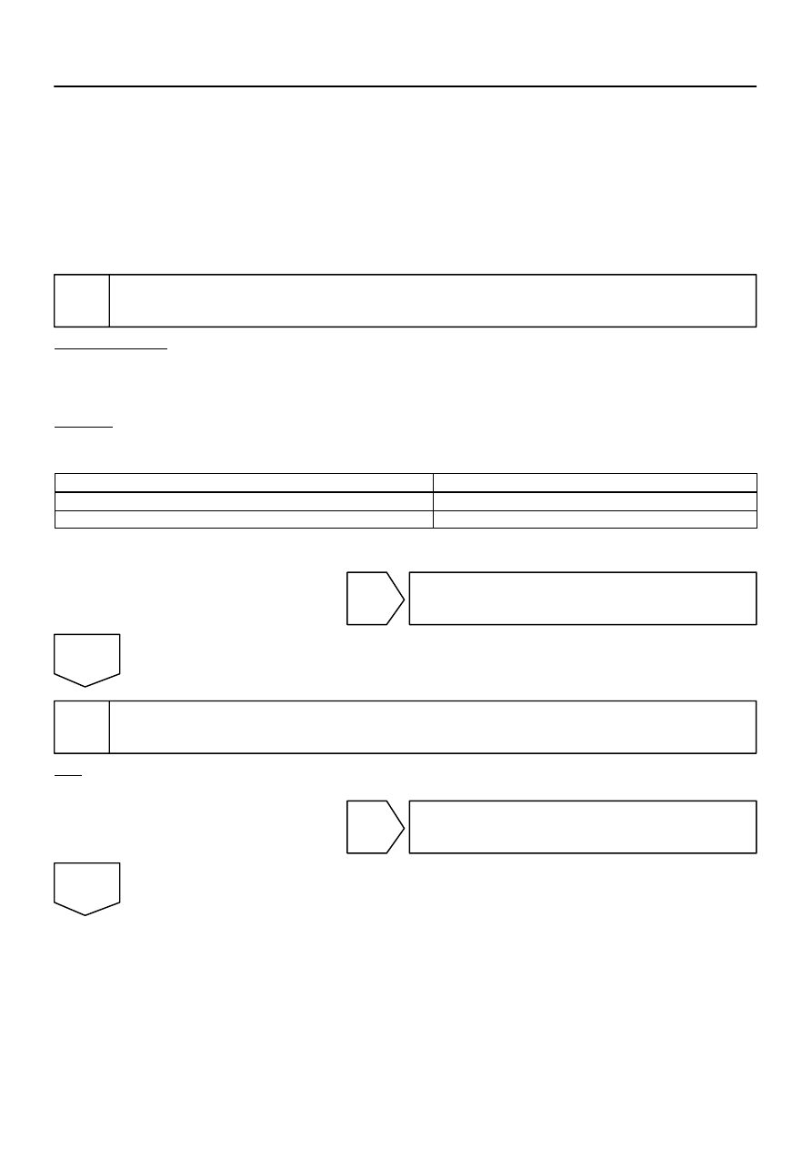
1
Check any other DTCs output (in addition to DTC P0171, P0172, P0174 or P0175).
PREPARATION:
(a)
Connect a hand–held tester to the DLC3.
(b)
Turn the ignition switch to ON and turn the tester ON.
(c)
Select the following menu items: DIAGNOSIS / ENHANCED OBD II / DTC INFO / CURRENT CODES.
CHECK:
(a)
Read DTCs.
Result:
Display (DTC Output)
Proceed To
P0171, P0172, P0174 or P0175
A
P0171, P0172, P0174 or P0175 and other DTCs
B
HINT:
If any DTCs other than P0171, P0172, P0174 or P0175 are output, troubleshoot those DTCs first.
B
).
A
2
Check connection of PCV piping.
OK:
PCV hose is connected correctly and is not damaged.
NG
Repair or replace PCV piping.
OK
Нет комментариевНе стесняйтесь поделиться с нами вашим ценным мнением.
Текст