Toyota Sequoia (2005). Manual — part 455

–
DIAGNOSTICS
COMBINATION METER SYSTEM
DI–1615
1809
Seat belt warning lamp for driver’s seat does not operate.
Refer to troubleshooting procedures
SLIP warning light does not come on.
1. SLIP warning light circuit
2. Wire harness and connector
3. Combination meter assy
4. Skid control ECU
–
INDICATOR LIGHTS:
Symptom
Suspected Area
See page
Turn indicator light does not come on.
1. Turn signal flasher relay
2. Wire harness or connector
3. Combination meter assy
–
High beam indicator light does not come on.
1. Headlight dimmer switch (*1)
Headlight dimmer switch circuit (*2)
2. Wire harness or connector
3. Combination meter assy
–
Washer level indicator light does not come on.
1. Washer level warning switch
2. Wire harness or connector
3. Combination meter assy
–
Tire pressure indicator light does not come on.
1. Tire pressure monitor ECU
2. Wire harness or connector
3. Combination meter assy
–
CRUISE main indicator light does not come on.
1. CRUISE main indicator light circuit
2. Cruise main control switch circuit
3. Wire harness or connector
4. Combination meter assy
–
VSC OFF indicator light does not come on.
1. VSC OFF indicator light circuit
2. Combination meter assy
VSC TRAC indicator light does not come on.
1. VSC TRAC indicator light circuit
2. Combination meter assy
Security indicator light does not come on.
1. Security indicator light circuit
2. Combination meter assy
4HI indicator light does not come on.
1. Wire harness and connector
2. Combination meter assy
3. 4WD control ECU
–
4LO indicator light does not come on.
1. Wire harness and connector
2. Combination meter assy
3. 4WD control ECU
–
CTR DIF LOCK indicator light does not come on.
1. Wire harness and connector
2. Combination meter assy
3. 4WD control ECU
–
Height control indicator lamp does not come on.
1. Height control indicator lamp circuit
2. Combination meter assy
Height control manual indicator lamp does not come on.
1. Height control manual indicator lamp circuit
2. Combination meter assy
A/T indicator light does not come on.
1. Park/neutral position switch circuit
2. Wire harness and connector
3. Combination meter assy
–
*1: w/o Day time running light
*2: w/ Day time running light
OTHERS:
Symptom
Suspected Area
See page
All buzzers (key reminder, seat belt) do not operate.
Combination meter assy
DID8V–01
I27709
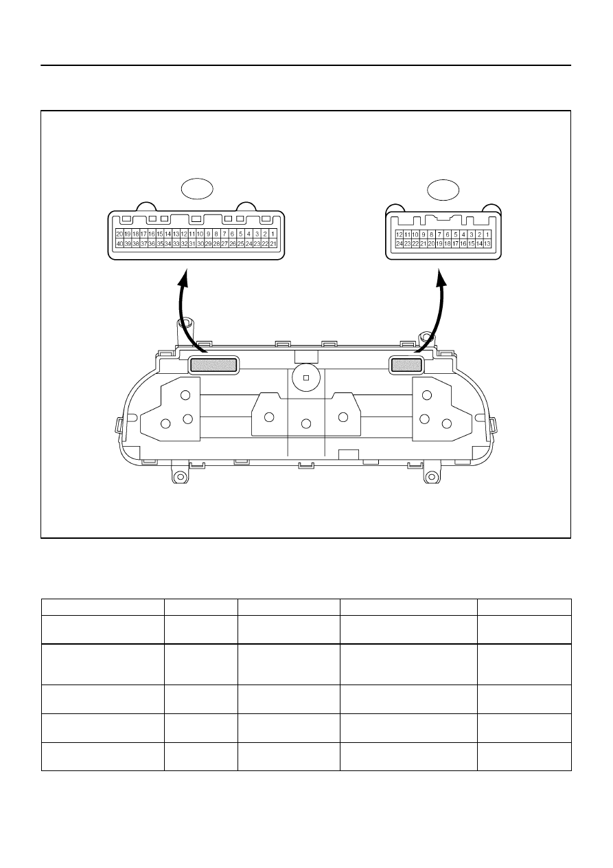
C5
C6
DI–1616
–
DIAGNOSTICS
COMBINATION METER SYSTEM
1810
TERMINALS OF ECU
COMBINATION METER ASSY
(a)
Disconnect the C5 and C6 connectors.
(b)
Measure the resistance of each terminal of the wire harness side connector.
Standard:
Terminals No.
Wiring Color
Terminal Description
Condition
Specified Condition
C5–5 – Body ground
L–W – Body
ground
Compass and garage
door opener
Always
Below 1
Ω
C5–6 – Body ground
L–R – Body
ground
Compass and garage
door opener communica-
tion line
Always
Below 1
Ω
C5–30 (*2) – Body ground
W – Body ground
Multiplex communication
signal
Always
Below 1
Ω
C5–31 – Body ground
LG–R – Body
ground
Multiplex communication
signal
Always
Below 1
Ω
C5–32 – Body ground
LG–B – Body
ground
Multiplex communication
signal
Always
Below 1
Ω

–
DIAGNOSTICS
COMBINATION METER SYSTEM
DI–1617
1811
(c)
Reconnect the C5 and C6 connectors.
(d)
Measure the voltage of each terminal of the wire harness side connector.
Standard:
Terminals No.
Wiring Color
Terminal Description
Condition
Specified Condition
C5–1 – Body ground
R–B – Body
ground
Parking brake signal
Parking brake warning light ON
6.7 to 12 V
C5–1 – Body ground
R–B – Body
ground
Parking brake signal
Parking brake warning light OFF
Below 1 V
C5–2 – Body ground
LG–R – Body
ground
CRUISE signal
CRUISE indicator light ON
Below 1 V
C5–2 – Body ground
LG–R – Body
ground
CRUISE signal
CRUISE indicator light OFF
10 to 14 V
C5–3 – Body ground
B – Body ground
Ignition switch signal
(Start)
Ignition switch OFF
Below 1 V
C5–3 – Body ground
B – Body ground
Ignition switch signal
(Start)
Ignition switch START
10 to 14 V
C5–4 – Body ground
G–Y – Body
ground
Seat belt condition signal
(Driver side)
D–BELT indicator light ON
Below 1 V
C5–4 – Body ground
G–Y – Body
ground
Seat belt condition signal
(Driver side)
D–BELT indicator light OFF
10 to 14 V
C5–13 – Body ground
LG–R – Body
ground
Washer level signal
WASH LVL indicator light ON
Below 1 V
C5–13 – Body ground
LG–R – Body
ground
Washer level signal
WASH LVL indicator light OFF
10 to 14 V
C5–14 – Body ground
L–O – Body
ground
O/D OFF indicator signal
O/D OFF indicator light ON
Below 1 V
C5–14 – Body ground
L–O – Body
ground
O/D OFF indicator signal
O/D OFF indicator light OFF
10 to 14 V
C5–15 (*1) – Body ground
Y–R – Body
ground
A/T oil temperature signal
A/T OIL TEMP. warning light ON
Below 1 V
C5–15 (*1) – Body ground
Y–R – Body
ground
A/T oil temperature signal
A/T OIL TEMP. warning light OFF
10 to 14 V
C5–16 – Body ground
LG–B – Body
ground
Security indicator light
signal (Engine immobilizer
system)
Security indicator light ON
10 to 14 V
C5–16 – Body ground
LG–B – Body
ground
Security indicator light
signal (Engine immobilizer
system)
Security indicator light OFF
Below 1 V
C5–17 – Body ground
GR – Body
ground
Security indicator light
signal (Theft deterrent
system)
Security indicator light ON
10 to 14 V
C5–17 – Body ground
GR – Body
ground
Security indicator light
signal (Theft deterrent
system)
Security indicator light OFF
Below 1 V
C5–18 – Body ground
V–W – Body
ground
CHECK ENGINE signal
CHECK ENGINE warning light ON
Below 1 V
C5–18 – Body ground
V–W – Body
ground
CHECK ENGINE signal
CHECK ENGINE warning light OFF
10 to 14 V
C5–19 – Body ground
G–B – Body
ground
A/T shift position signal
(L)
A/T L indicator OFF
Below 1 V

DI–1618
–
DIAGNOSTICS
COMBINATION METER SYSTEM
1812
C5–19 – Body ground
G–B – Body
ground
A/T shift position signal
(L)
A/T L indicator ON
10 to 14 V
C5–20 – Body ground
GR–L – Body
ground
Tire pressure signal
Tire pressure warning light ON
6.7 to 12 V
C5–20 – Body ground
GR–L – Body
ground
Tire pressure signal
Tire pressure warning light OFF
Below 1 V
C5–21 – Body ground
R – Body ground
Injector signal
Ignition switch ON
Pulse generation
C5–22 – Body ground
W–G – Body
ground
Illumination signal
Light control switch OFF
Below 1 V
C5–22 – Body ground
W–G – Body
ground
Illumination signal
Light control switch ON
10 to 14 V
C5–23 – Body ground
Y–G – Body
ground
Tachometer signal
Engine running
Pulse generation
(see waveform 1)
C5–24 – Body ground
Y – Body ground
Speed signal (Input)
Ignition switch ON and turn the
wheel slowly
10 to 14 V
↔
Below 1 V
C5–25 – Body ground
G–O – Body
ground
Speed signal (Output)
Ignition switch ON and turn the
wheel slowly
Pulse generation
(see waveform 2)
C5–26 – Body ground
V – Body ground
Power source for fuel
sender gauge
Ignition switch ON, fuel level is
FULL
Below 1 V
C5–26 – Body ground
V – Body ground
Power source for fuel
sender gauge
Ignition switch ON, fuel level is
EMPTY
4 to 7 V
C5–27 – Body ground
L–B – Body
ground
Oil pressure signal
Oil pressure warning light ON
Below 1 V
C5–27 – Body ground
L–B – Body
ground
Oil pressure signal
Oil pressure warning light OFF
10 to 14 V
C5–28 – Body ground
B–R – Body
ground
Injector power signal
Ignition switch ON
10 to 14 V
C5–29 – Body ground
B–Y – Body
ground
SRS warning light signal
SRS warning light ON
Below 1 V
C5–29 – Body ground
B–Y – Body
ground
SRS warning light signal
SRS warning light OFF
8 to 14 V
C5–33 – Body ground
G–Y – Body
ground
Turn signal (R)
Ignition switch ON, turn signal RH
indicator OFF
Below 1 V
C5–33 – Body ground
G–Y – Body
ground
Turn signal (R)
Ignition switch ON, turn signal RH
indicator ON
10 to 14 V
C5–34 – Body ground
L–Y – Body
ground
A/T shift position signal
(P)
A/T P indicator OFF
Below 1 V
C5–34 – Body ground
L–Y – Body
ground
A/T shift position signal
(P)
A/T P indicator ON
10 to 14 V
C5–35 – Body ground
B–Y – Body
ground
A/T shift position signal
(R)
A/T R indicator OFF
Below 1 V
C5–35 – Body ground
B–Y – Body
ground
A/T shift position signal
(R)
A/T R indicator ON
10 to 14 V
C5–36 – Body ground
G–R – Body
ground
A/T shift position signal
(N)
A/T N indicator OFF
Below 1 V
C5–36 – Body ground
G–R – Body
ground
A/T shift position signal
(N)
A/T N indicator ON
10 to 14 V
C5–37 – Body ground
W–R – Body
ground
A/T shift position signal
(D)
A/T D indicator OFF
Below 1 V
Нет комментариевНе стесняйтесь поделиться с нами вашим ценным мнением.
Текст