Toyota Sequoia (2005). Manual — part 814
F06734
Plate Washer A
Plate Washer B
SST
Screw
R12472
SST
Retaining Ring
SR–18
–
STEERING
TILT STEERING COLUMN
3245
9.
REMOVE STEERING COLUMN HOUSING WITH MAIN
SHAFT ASSEMBLY
(a)
Set SST, 2 plate washers (18 and 36 mm outer diameter)
and a screw (4.0 mm diameter, 0.7 mm pitch, 15.0 mm
length), as shown in the illustration. Then remove the 2
pivot pins.
SST
09910–00015 (09911–00011, 09912–00010)
Reference
Plate washer A (18 mm): 90562–04012
Plate washer B (36 mm): 90201–10201
Screw: 90154–40015
(b)
Remove the column housing with the shaft assembly from
the column tube assembly.
NOTICE:
Do not bend the universal joint of the main shaft assembly
more than 15
°
.
(c)
Remove the tilt spring and spring guide.
10.
REMOVE 2 TILT NO. 1 STOPPERS
11.
REMOVE MAIN SHAFT STOPPER
12.
REMOVE MAIN SHAFT ASSEMBLY
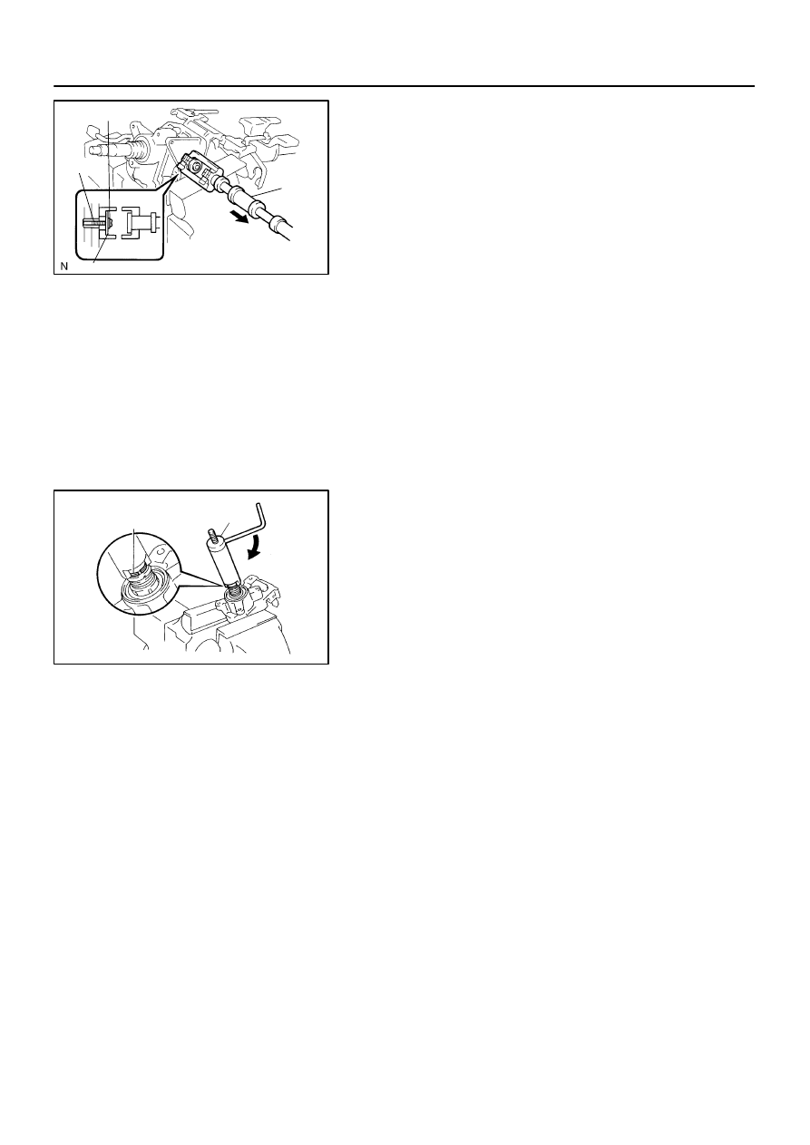
(a)
Install SST to the main shaft assembly, as shown in the
illustration.
SST
09612–07010
(b)
Using SST, compress the compression spring.
SST
09612–07010
NOTICE:
Do not bend the universal joint of the shaft assembly more
than 15
°
.
HINT:
Hold the shaft assembly with your hand to prevent rotation.
(c)
Using a screwdriver, remove the No. 2 steering column
ring.
(d)
Remove the spring retainer, compression spring, upper
bearing inner race seat and inner race.
13.
REMOVE TILT LEVER
Remove the tilt lever lock shaft and shift lever.
SR0V2–05
F13613
F13618
R11908
–
STEERING
TILT STEERING COLUMN
SR–19
3246
INSPECTION
1.
INSPECT STEERING LOCK OPERATION
Check that the steering lock mechanism operates properly.
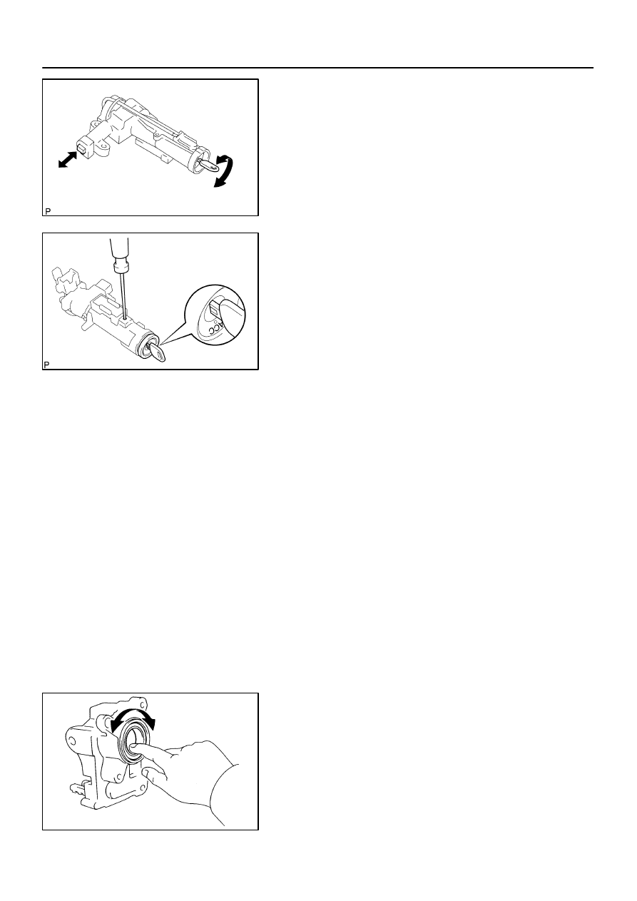
2.
IF NECESSARY, REPLACE KEY CYLINDER
(a)
Turn the ignition key to the ACC position.
(b)
Push down the stop pin with a screwdriver, and pull out
the cylinder.
(c)
Install a new cylinder.
HINT:
Make sure that the key is in the ACC position.
3.
INSPECT IGNITION SWITCH (See page
4.
IF NECESSARY, REPLACE IGNITION SWITCH
(a)
Remove the 2 screws and ignition switch.
(b)
Install a new ignition switch with the 2 screws.
5.
INSPECT KEY UNLOCK WARNING SWITCH
(See page
6.
IF NECESSARY, REPLACE KEY UNLOCK WARNING
SWITCH
(a)
Slide out the key unlock warning switch.
(b)
Install a new key unlock warning switch.
7.
INSPECT TRANSPONDER KEY COIL
(See page
8.
IF NECESSARY, REPLACE TRANSPONDER KEY
COIL
9.
IF NECESSARY, REPLACE TRANSPONDER KEY AM-
PLIFIER
(a)
Remove the screw and transponder key amplifier.
(b)
Install a new transponder key amplifier with the screw.
10.
INSPECT BEARING
(a)
Check that the bearing rotates smoothly without abnor-
mal noise.
If it does not rotate smoothly or abnormal noise occurs, replace
the column housing.
(b)
Coat the bearing with molybdenum disulfide lithium base
grease.
F13614
SST
Shaft Bearing
F13615
SST
Shaft Bearing
SR–20
–
STEERING
TILT STEERING COLUMN
3247
11.
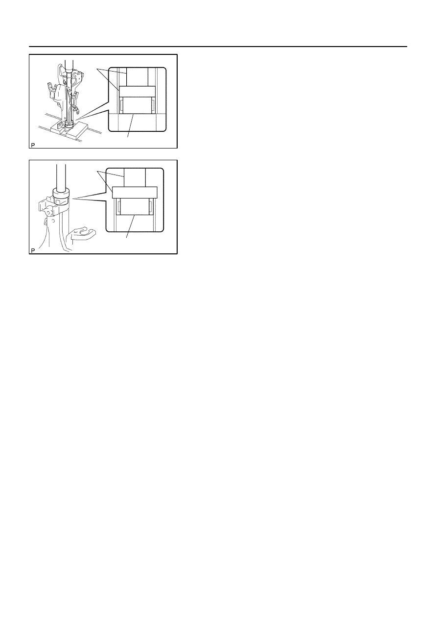
IF NECESSARY, REPLACE SHAFT BEARING
(a)
Using SST and a press, press out the shaft bearing.
SST
09950–60010 (09951–00400),
09950–70010 (09951–07360)
(b)
Coat a new shaft bearing with molybdenum disulfide lithi-
um base grease.
(c)
Using SST and a press, press in the shaft bearing.
SST
09950–60010 (09951–00460),
09950–70010 (09951–07150)
SR0V3–05
R12807
Washer
Retaining Ring
SST
F06735
F06736
–
STEERING
TILT STEERING COLUMN
SR–21
3248
REASSEMBLY
NOTICE:
When using a vise, do not overtighten it.
1.
COAT PARTS INDICATED BY ARROWS WITH MOLYB-
DENUM DISULFIDE LITHIUM BASE GREASE (See
page
)
2.
INSTALL TILT LEVER
Install the tilt lever with a new tilt lever lock shaft.
Torque: 9.0 N·m (90 kgf·cm, 78 in.·lbf)
3.
INSTALL MAIN SHAFT ASSEMBLY
(a)
Install the inner race, upper bearing inner race seat, com-
pression spring and spring retainer.
(b)
Install a new No. 2 steering column ring to the main shaft
assembly.
(c)
Install the washer of SST on the main shaft assembly.
SST
09612–07010
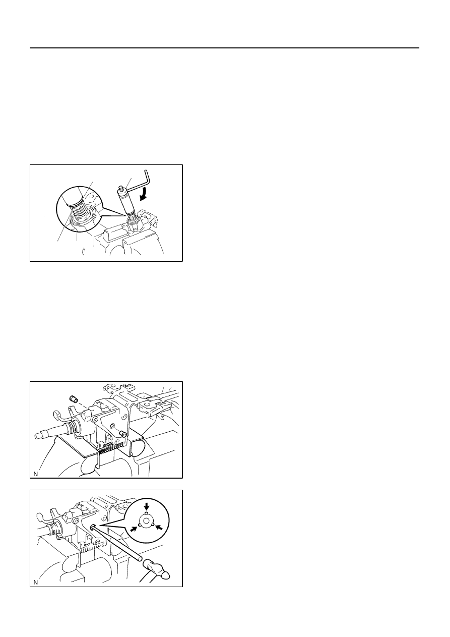
(d)
Set SST on the main shaft assembly, as shown in the il-
lustration.
SST
09612–07010
(e)
Using SST, push down the retaining ring until it fits into the
shaft groove and install the main shaft assembly.
NOTICE:
Do not bend the universal joint of the shaft assembly more
than 15
°
.
HINT:
Hold the main shaft assembly with your hand to prevent rota-
tion.
4.
INSTALL MAIN SHAFT STOPPER
5.
INSTALL 2 NEW TILT NO. 1 STOPPERS
6.
INSTALL STEERING COLUMN HOUSING WITH MAIN
SHAFT ASSEMBLY
(a)
Install the steering column housing with the main shaft as-
sembly into the column tube assembly.
(b)
Install the tilt spring and spring guide.
(c)
Hold the steering column housing and steering column
housing support in a vise.
(d)
Temporarily install 2 new pivot pins.
(e)
Using a punch and a hammer, tap in the pivot pin.
(f)
Using a pin punch and a hammer, stake at 3 places evenly
around the hole as shown in the illustration.
Нет комментариевНе стесняйтесь поделиться с нами вашим ценным мнением.
Текст