Toyota Sequoia (2005). Manual — part 813
SR1KD–01
F17124
Screw Case
Torx
®
Screw
F17904
Correct
Wrong
Airbag Connectors
F06699
Matchmarks
SST
SR–14
–
STEERING
TILT STEERING COLUMN
3241
REMOVAL
1.
DISCONNECT CABLE FROM NEGATIVE BATTERY
TERMINAL
Wait for 90 seconds after disconnecting the cable to prevent the
airbag working.
2.
REMOVE STEERING WHEEL PAD
NOTICE:
If the airbag connector is disconnected with the ignition
switch in the ACC or ON position, DTCs will be recorded.
(a)
Place the front wheels facing straight ahead.
(b)
Remove the steering wheel lower No. 3 cover.
(c)
Remove the steering wheel lower No. 2 cover.
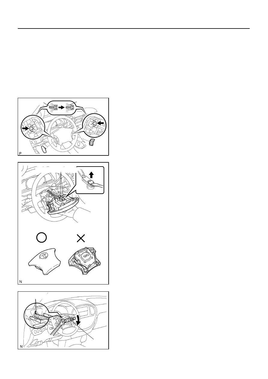
(d)
Using a torx
®
socket wrench (T30), loosen the 2 torx
®
screws.
HINT:
Loosen each screw until the groove along the screw circumfer-
ence is caught on the screw case.
(e)
Pull out the wheel pad from the steering wheel.
(f)
Using a screwdriver, disconnect the airbag connectors.
CAUTION:
When storing the steering wheel pad, keep the upper
surface of the pad facing upward.
Never disassemble the steering wheel pad.
NOTICE:
When removing the steering wheel pad, take care not to
pull the airbag wire harness.
(g)
Disconnect the horn terminal and remove the steering
wheel pad.
3.
REMOVE STEERING WHEEL
(a)
Remove the steering wheel set nut.
(b)
Put matchmarks on the steering wheel and main shaft as-
sembly.
(c)
Using SST, remove the wheel.
SST
09950–50013 (09951–05010, 09952–05010,
09953–05020, 09954–05021)
4.
REMOVE UPPER AND LOWER COLUMN COVERS
Remove the 3 screws, upper and lower column covers.
F17896
A
B
Matchmarks
F13260
F06703
–
STEERING
TILT STEERING COLUMN
SR–15
3242
5.
REMOVE COMBINATION SWITCH WITH SPIRAL
CABLE
(a)
Disconnect the 4 connectors.
(b)
Disconnect the airbag connector.
(c)
Remove the 3 screws and combination switch.
6.
REMOVE SPIRAL CABLE (See page
NOTICE:
Do not disassemble the cable or apply oil to it.
7.
REMOVE COWL SIDE TRIM AND FRONT DOOR
SCUFF PLATE
8.
REMOVE LOWER LH FINISH PANEL
(a)
Remove the 2 screws and disconnect the hood lock re-
lease lever from the panel.
(b)
Remove the 4 panel set bolts and lower LH finish panel.
9.
REMOVE NO. 2 HEATER TO REGISTER DUCT
10.
REMOVE BRAKE PEDAL RETURN SPRING
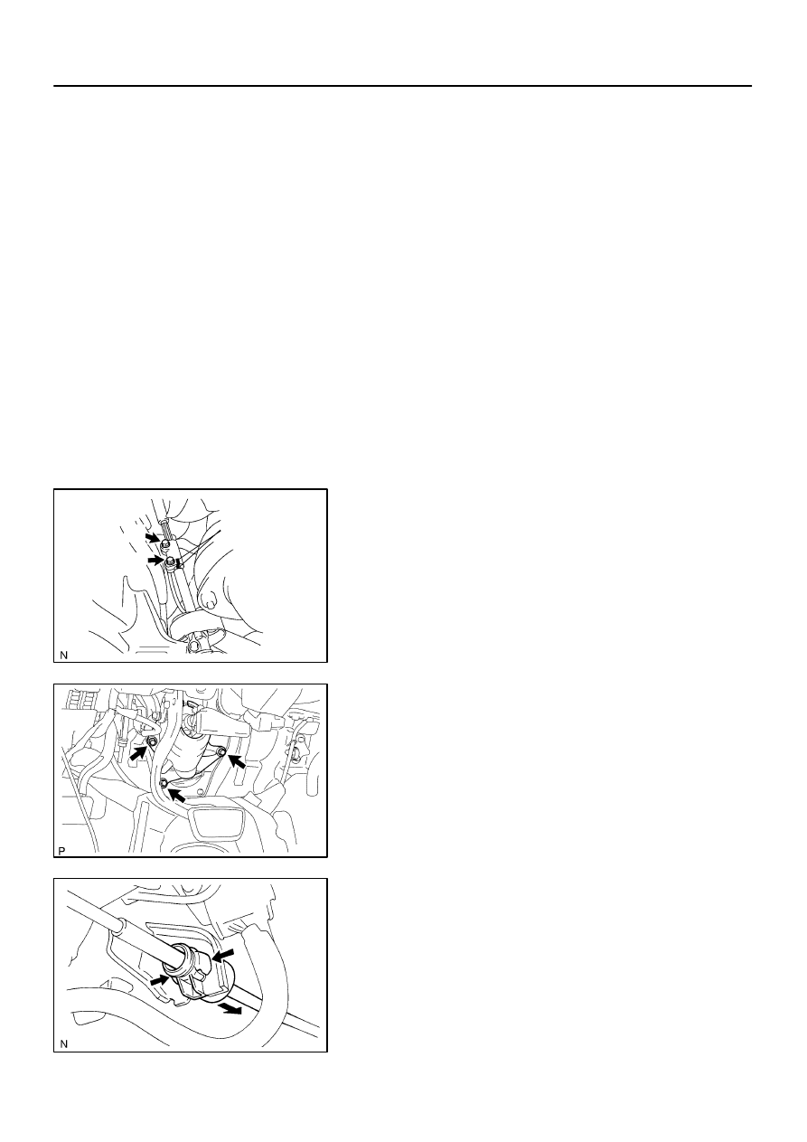
11.
REMOVE SLIDING YOKE
(a)
Put matchmarks on the sliding yoke and No. 2 intermedi-
ate shaft assembly.
(b)
Remove the ”A” bolt.
(c)
Remove the ”B” bolt.
(d)
Slide the sliding yoke and remove it.
12.
REMOVE COLUMN HOLE COVER NO. 2
Remove the 3 bolts and column hole cover No. 2.
13.
DISCONNECT TRANSMISSION CONTROL CABLE
ASSEMBLY
Disconnect the cable assembly from the column shift lever as-
sembly.
14.
REMOVE STEERING COLUMN ASSEMBLY WITH
NO. 2 UNIVERSAL JOINT ASSEMBLY
(a)
Disconnect the connectors.
(b)
Remove the 4 steering column set nuts.
(c)
Pull out the steering column assembly with the No. 2 uni-
versal joint assembly connected.
F17913
Matchmarks
F17897
Matchmarks
SR–16
–
STEERING
TILT STEERING COLUMN
3243
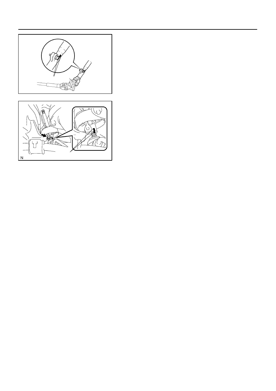
15.
REMOVE NO. 2 UNIVERSAL JOINT ASSEMBLY
(a)
Put matchmarks on the steering column assembly and
No. 2 universal joint assembly.
(b)
Remove the bolt and No. 2 universal joint assembly.
16.
REMOVE NO. 2 INTERMEDIATE SHAFT ASSEMBLY
(a)
Put matchmarks on the No. 2 intermediate shaft assem-
bly and control valve shaft.
(b)
Remove the bolt and No. 2 intermediate shaft assembly.
SR0V1–06
F13611
Screw Extractor
F06733
–
STEERING
TILT STEERING COLUMN
SR–17
3244
DISASSEMBLY
NOTICE:
When using a vise, do not overtighten it.
1.
REMOVE TRANSPONDER KEY COIL
2.
REMOVE KEY CYLINDER LAMP ASSEMBLY
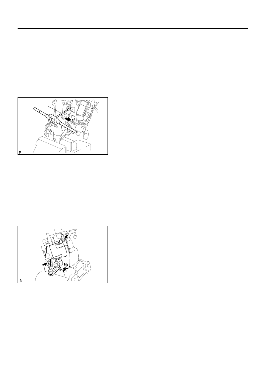
3.
REMOVE COLUMN UPPER BRACKET
(a)
Using a centering punch, mark the center of the 2 ta-
pered–head bolts.
(b)
Using a 3 to 4 mm (0.12 to 0.16 in.) drill, drill a hole into
the 2 bolts.
(c)
Using a screw extractor, remove the 2 bolts and column
upper bracket.
4.
REMOVE SHIFT LEVER
Using a torx
®
socket wrench, remove the torx
®
screw and shift
lever.
5.
REMOVE PARK LOCK CABLE ASSEMBLY
(See page
)
6.
REMOVE SHIFT LEVER HOUSING
Using a torx
®
socket wrench, remove the 3 torx
®
screws and
shift lever housing.
7.
REMOVE RELEASE LEVER SPRING
8.
REMOVE TURN SIGNAL BRACKET
Using a torx
®
socket wrench, remove the 2 torx
®
screws and
turn signal bracket.
Нет комментариевНе стесняйтесь поделиться с нами вашим ценным мнением.
Текст