Toyota Sequoia (2005). Manual — part 123
B17447
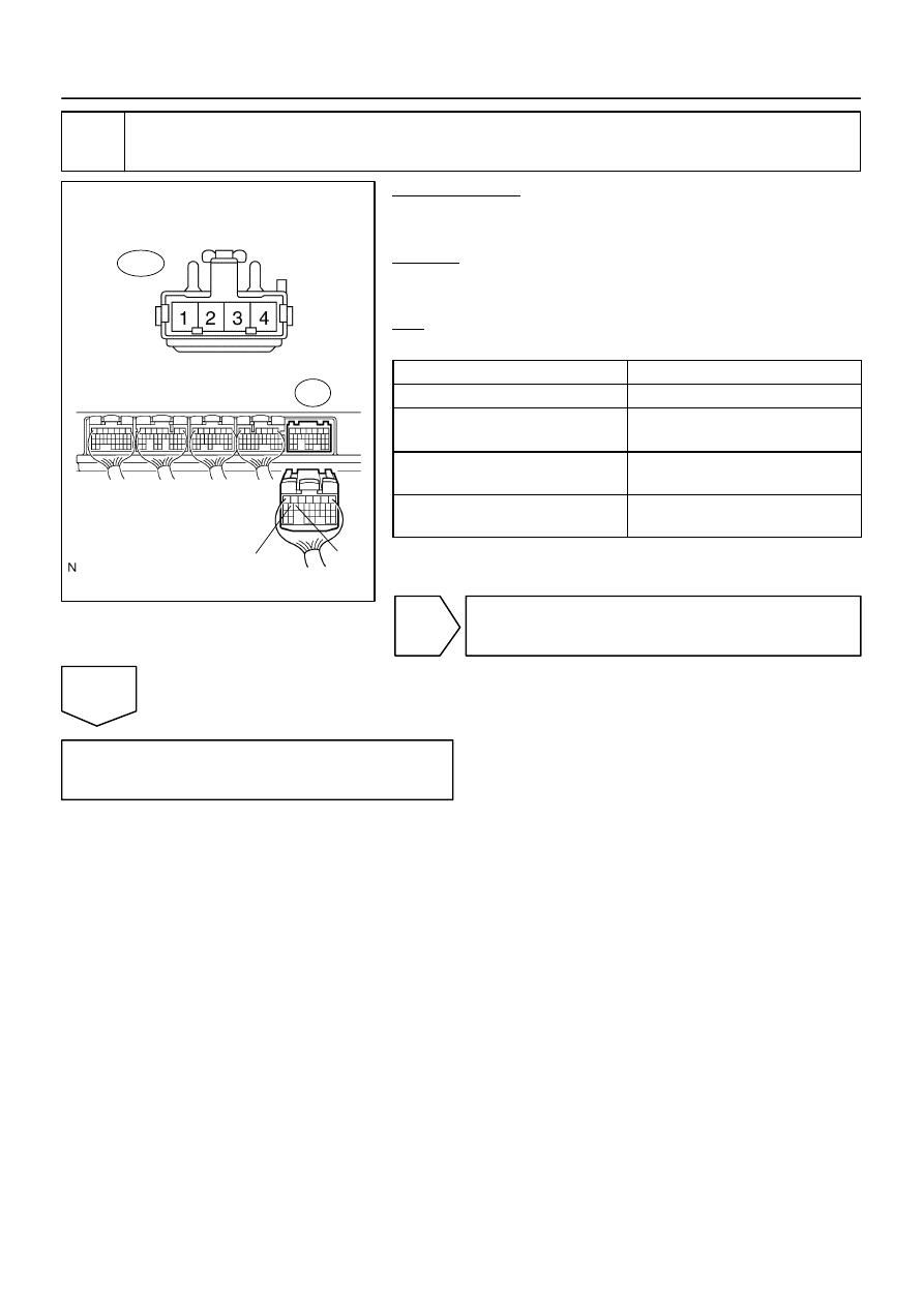
Wire Harness Side:
Stop Light Switch Connector
S14
ST1–
STP
E4
–
DIAGNOSTICS
ENGINE
DI–287
481
4
Check harness and connector between ECM and stop light switch.
PREPARATION:
(a)
Disconnect the S14 stop light switch connector.
(b)
Disconnect the E4 ECM connector.
CHECK:
Measure the resistance between the wire harness side connec-
tors.
OK:
Standard:
Tester Connection
Specified Condition
Stop light switch (S14–1) – STP (E4–15)
Below 1
Ω
Stop light switch (S14–3) – ST1–
(E4–16)
Below 1
Ω
Stop light switch (S14–1) or
STP (E4–15) – Body ground
10 k
Ω
or higher
Stop light switch (S14–3) or
ST1– (E4–16) – Body ground
10 k
Ω
or higher
NG
Repair or replace harness or connector.
OK
Replace ECM (See page
A20823
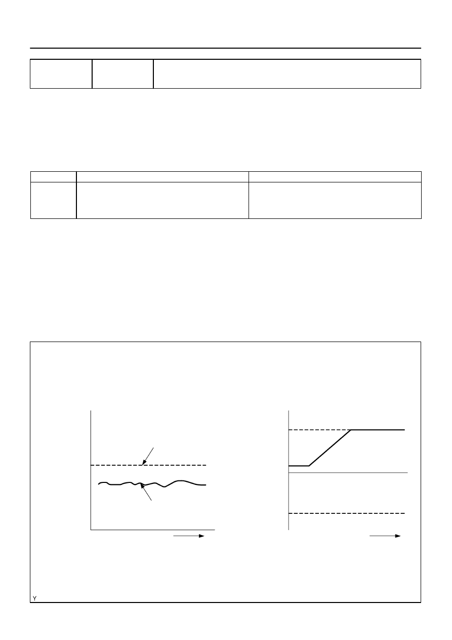
Idle engine
RPM
Small
Target RPM
Actual idle RPM
Large
Learned value
of the idle speed
control
Maximum
Minimum
Time
0
Time
DI–288
–
DIAGNOSTICS
ENGINE
482
DTC
P0505
Idle Air Control System
CIRCUIT DESCRIPTION
The idle speed is controlled by the ETCS (Electronic Throttle Control System).
The ETCS is composed of the throttle motor which operates the throttle valve, and the throttle position sen-
sor, which detects the opening angle of the throttle valve.
The ECM controls the throttle motor to provide the proper throttle valve opening angle to obtain the target
idle speed.
DTC No.
DTC Detection Condition
Trouble Area
P0501
Idle speed continues to vary greatly from target speed
(2 trip detection logic)
ETCS
Air induction system
PCV hose connection
ECM
MONITOR DESCRIPTION
The ECM regulates the idle speed by opening and closing the throttle valve using the ETCS. The ECM con-
cludes that the idle speed control ECM function is malfunctioning if: 1) the actual idle RPM varies more than
the specified amount, or 2) a learning value of the idle speed control remains at the maximum or minimum
five times or more during a driving cycle. The ECM will turn on the MIL and set a DTC.
Example:
If the actual idle RPM varies from the target idle RPM by more than 100 (*1) rpm five times during a driving
cycle, the ECM will turn on the MIL and a DTC is set.
HINT:
*1: RPM threshold varies with engine load.
DICF6–02
–
DIAGNOSTICS
ENGINE
DI–289
483
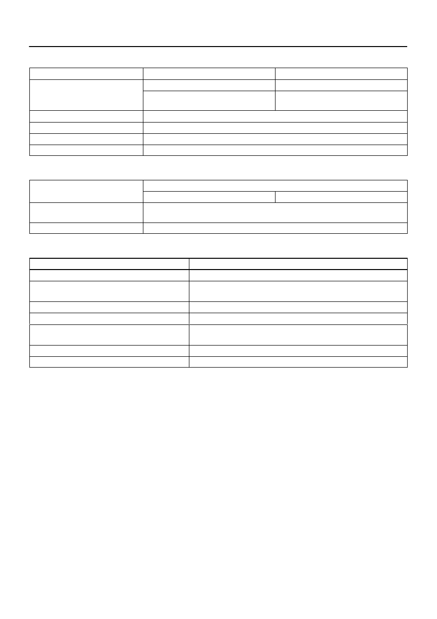
MONITOR STRATEGY
Related DTCs
P0505
Idle air control malfunction
Main sensors/components
Crankshaft position sensor
Required sensors/components
Related sensors/components
Vehicle speed sensor, Engine coolant tempera-
ture sensor
Frequency of operation
Once per driving cycle
Duration
10 min.
MIL operation
2 driving cycles
Sequence of operation
None
TYPICAL ENABLING CONDITIONS
It
Specification
Item
Minimum
Maximum
The monitor will run whenever this DTC is
not present
See page
Engine
Running
TYPICAL MALFUNCTION THRESHOLDS
Detection Criteria
Threshold
Either of the following conditions is met:
Condition 1 or 2
1. Frequency that both of the following conditions (a) and (b)
are met:
5 times or more
(a) Engine RPM – target engine RPM
Less than –100 rpm or more than 150 rpm
(b) Vehicle condition
Stop after vehicle was driven by 10 km/h (6.25 mph) or more
2. Frequency that both of the following conditions (a) and (b)
are met:
Once
(a) Engine RPM – target engine RPM
Less than –100 rpm or more than 150 rpm
(b) Intake air control flow rate learning value
2.48 L/sec. or less, or 11 L/sec. or more
DI–290
–
DIAGNOSTICS
ENGINE
484
INSPECTION PROCEDURE
HINT:
When the throttle position is slightly opened (the accelerator pedal is slightly depressed) because a
floor carpet is overlapped on the accelerator pedal, or if the accelerator pedal is not fully released, etc.,
DTC P0505 will possibly be detected.
Read freeze frame data using
the hand−held tester
. Freeze frame data records the engine conditions
when a malfunction is detected. When troubleshooting, freeze frame data can help determine if the
vehicle was running or stopped, if the engine was warmed up or not, if the air–fuel ratio was lean or
rich, as well as other data from the time when a malfunction occurred.
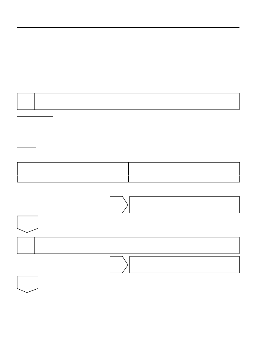
1
Are there any other codes (besides P0505) being output?
PREPARATION:
(a)
Connect the hand–held tester to the DLC3.
(b)
Turn the ignition switch ON and push the hand–held tester main switch ON.
(c)
When using hand–held tester, enter the following menu: DIAGNOSIS / ENHANCED OBD II / DTC
INFO / CURRENT CODES.
CHECK:
Read the DTC using the hand–held tester.
RESULT:
Display (DTC Output)
Proceed to
P0505
A
”P0505” and other DTCs
B
HINT:
If any other codes besides P0505 are output, perform the troubleshooting for those DTCs first.
B
Go to relevant DTC chart (See page
A
2
Check connection of PCV piping.
NG
Repair or replace PCV piping.
OK
Нет комментариевНе стесняйтесь поделиться с нами вашим ценным мнением.
Текст