Toyota Sequoia (2005). Manual — part 121
A23556
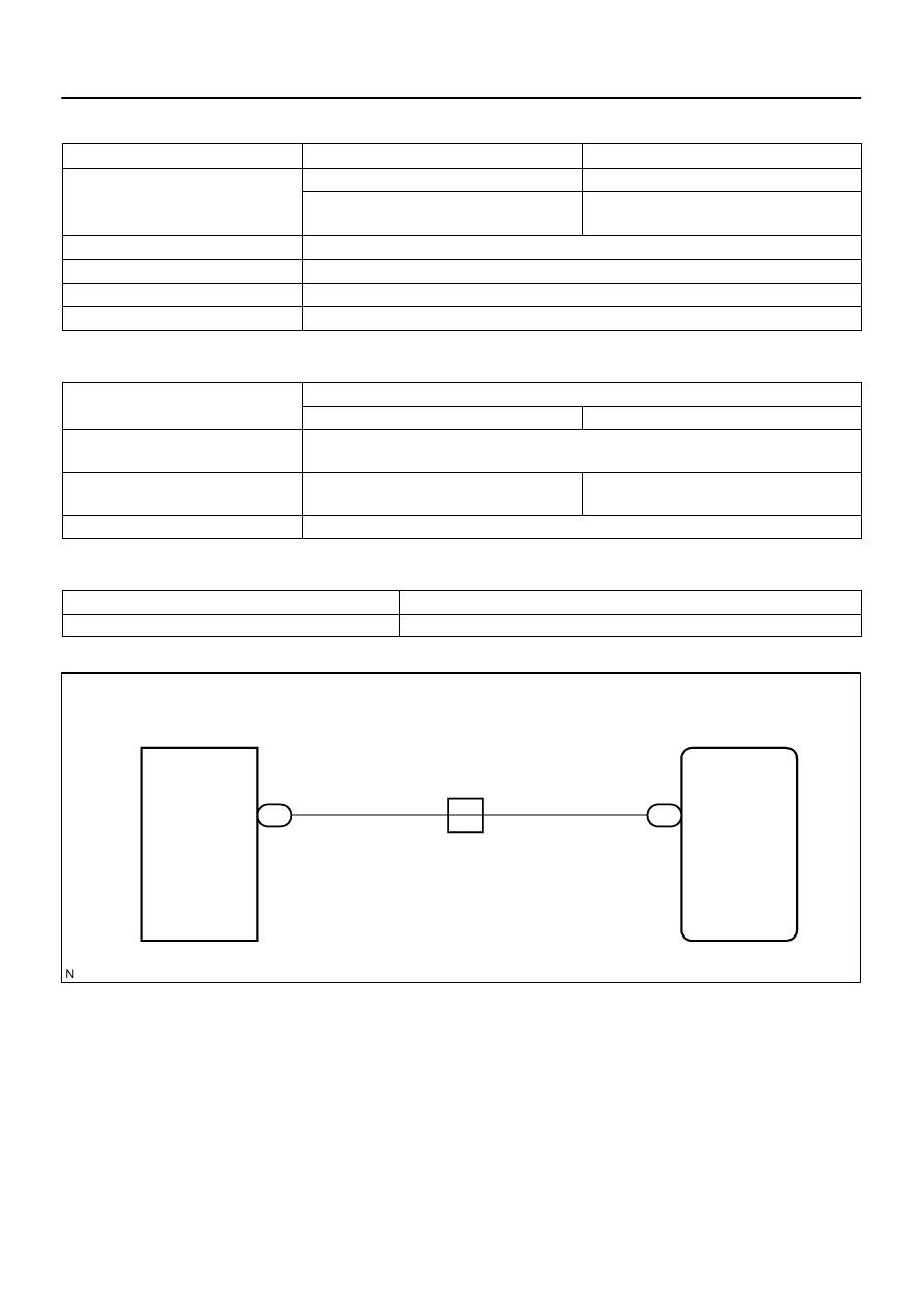
8
J17
J/C
ECM
Combination Meter
SPD
E5
G–O
B
G–O
25
C5
B
–
DIAGNOSTICS
ENGINE
DI–279
473
MONITOR STRATEGY
Related DTCs
P0500
Vehicle speed sensor ”A” pulse input error
Main sensors
Vehicle speed sensor
Required sensors/components
Related sensors
Park/Neutral position switch, Engine coolant tem-
perature sensor, Combination meter
Frequency of operation
Continuous
Duration
500 times
MIL operation
Immediate
Sequence of operation
None
TYPICAL ENABLING CONDITIONS
It
Specification
Item
Minimum
Maximum
The monitor will run whenever this DTC is
not present
See page
Vehicle speed is 9 km/h (5.59 mph) or
more
4 sec.
–
Park/neutral position switch
OFF
TYPICAL MALFUNCTION THRESHOLDS
Detection Criteria
Threshold
Sensor signal
No pulse input
WIRING DIAGRAM

DI–280
–
DIAGNOSTICS
ENGINE
474
INSPECTION PROCEDURE
HINT:
Read freeze frame data using
the hand−held tester.
Freeze frame data records the engine conditions when
a malfunction is detected. When troubleshooting, freeze frame data can help determine if the vehicle was
running or stopped, if the engine was warmed up or not, if the air–fuel ratio was lean or rich, as well as other
data from the time when a malfunction occurred.
1
Check operation of speedometer.
PREPARATION:
(a)
Connect the hand–held tester to the DLC3.
(b)
Turn the ignition switch to ON and push the hand–held tester main switch ON.
(c)
Start the engine.
(d)
When using hand–held tester, enter the following menu: DIAGNOSIS / ENHANCED OBD II / DATA
LIST / PRIMARY / VEHICLE SPD.
CHECK:
Read the mass air flow rate on the hand–held tester.
RESULT:
Vehicle speed
Proceed to
Vehicle speed remains 0 km/h (0 mph)
A
Vehicle speed is lower than actual speed
A
Vehicle speed is same as actual speed
B
B
Check for intermittent problems
(See page
A
B17411
SPD(+)
E6
E5
E1
AT7809
4 to
6 V
Turn the Wheel
3
2
1
I25536
Component Side Connector:
Vehicle Speed Sensor
–
DIAGNOSTICS
ENGINE
DI–281
475
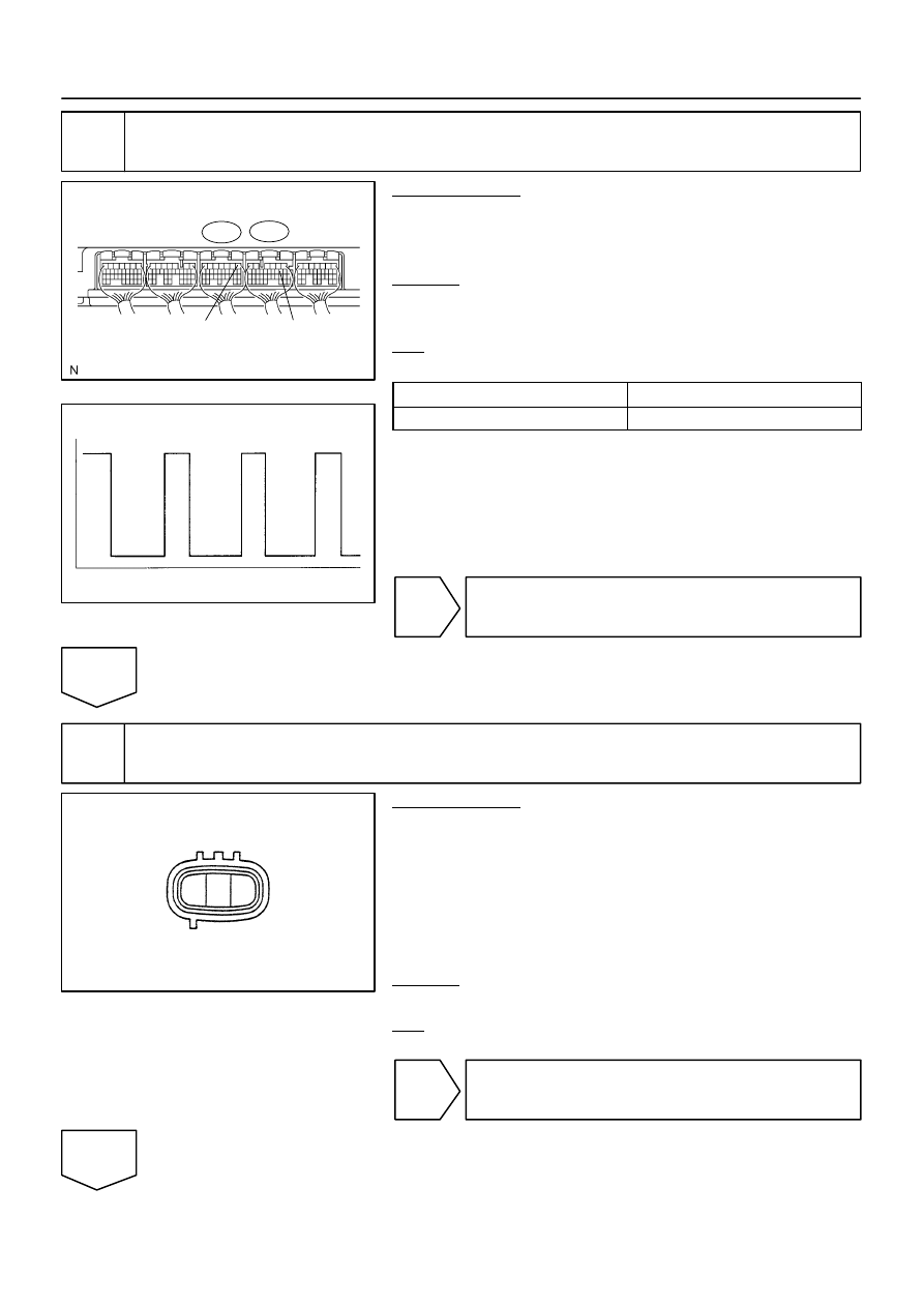
2
Check voltage between terminal SPD and E1 of ECM connector.
PREPARATION:
(a)
Shift the shift lever to neutral.
(b)
Jack up the rear wheel on one side.
(c)
Turn the ignition switch ON.
CHECK:
Measure the voltage between the specified terminal of the E5
and E6 ECM connector when the wheel is turned slowly.
OK:
Standard:
Tester Connection
Specified Condition
SPD (E5–8) – E1 (E6–1)
Generated intermittently
HINT:
The output voltage should fluctuate up and down similarly to the
diagram on the left when the wheel is turned slowly.
OK
Replace ECM (See page
NG
3
Check vehicle speed sensor.
PREPARATION:
(a)
Disconnect the vehicle speed sensor connector.
(b)
Connect the battery positive (+) lead to terminal 1 and the
battery negative (–) lead to terminal 2.
(c)
Connect the tester positive (+) lead to terminal 3 and the
tester negative (–) lead to terminal 2.
(d)
Shift the shift lever to N position.
(e)
Rotate the shaft.
CHECK:
Check that there is voltage change between terminals 2 and 3.
OK:
Standard: 0 V to 10 V or more
NG
Replace vehicle speed sensor.
OK
BR3795
OK
NG
Clearance
B17411
SPD(+)
E5
A23540
Wire Harness Side:
Front View
Combination Meter Connector
C5
DI–282
–
DIAGNOSTICS
ENGINE
476
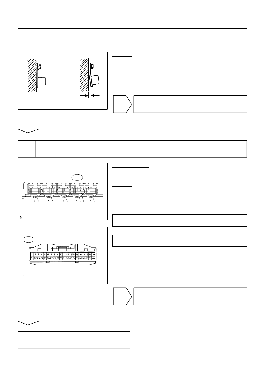
4
Check sensor installation (Vehicle speed sensor).
CHECK:
Check the vehicle speed sensor installation.
OK:
The vehicle speed sensor is installed properly.
NG
Tighten sensor installation bolt.
OK
5
Check for open and short in harness and connector between combination meter
and ECM.
PREPARATION:
(a)
Disconnect the C5 combination meter connector.
(b)
Disconnect the E5 ECM connector.
CHECK:
Check for resistance between the wire harness side connec-
tors.
OK:
Standard (Check for open):
Symbols (Terminal No.)
Specified condition
SPD (E5–8) – C5–25
Below 1
Ω
Standard (Check for short):
Symbols (Terminal No.)
Specified condition
SPD (E5–8) or C5–25 – Body ground
10 k
Ω
or higher
NG
Repair or replace harness or connector.
OK
Check combination meter circuit (See page
Нет комментариевНе стесняйтесь поделиться с нами вашим ценным мнением.
Текст