Toyota Sequoia (2005). Manual — part 714
LU08R–09
B02610
B02611
–
LUBRICATION
OIL PUMP
LU–11
2845
DISASSEMBLY
1.
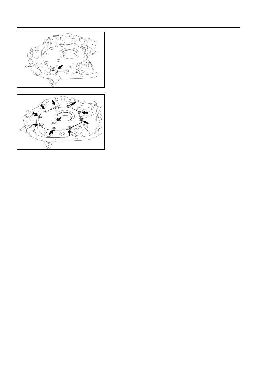
REMOVE RELIEF VALVE
Remove the plug, compression spring and relief valve.
2.
REMOVE DRIVE AND DRIVEN ROTORS
Remove the 10 screws, pump body cover, the drive and driven
rotors.
LU08S–07
B02609
B02613
B02614
B02615
LU–12
–
LUBRICATION
OIL PUMP
2846
INSPECTION
1.
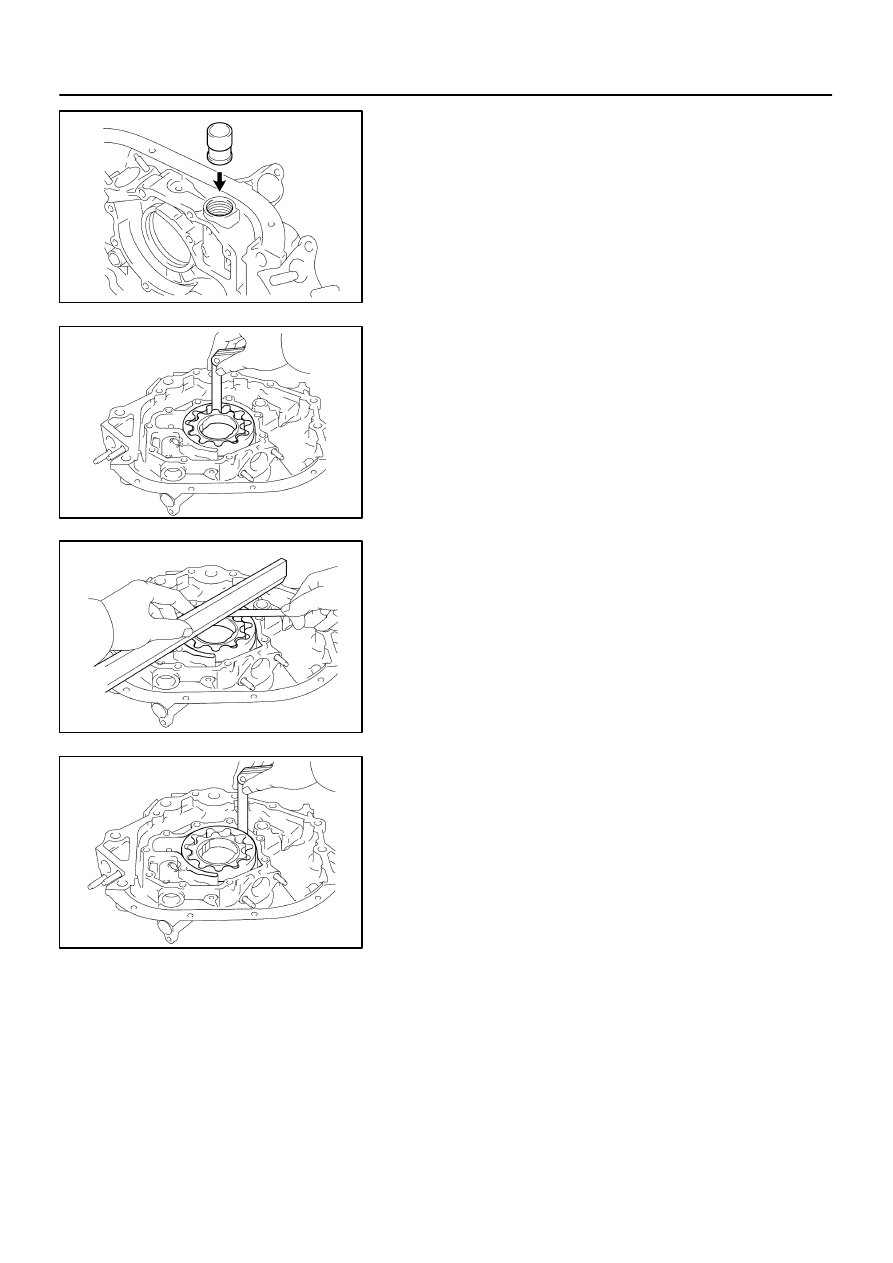
INSPECT RELIEF VALVE
Coat the valve with engine oil and check that it falls smoothly
into the valve hole by its own weight.
If it doesn’t, replace the relief valve. If necessary, replace the oil
pump assembly.
2.
INSPECT DRIVE AND DRIVEN ROTORS
(a)
Place the drive and driven rotors into the oil pump body.
(see page
(b)
Inspect the rotors for the body clearance.
Using a feeler gauge, measure the clearance between
the drive and driven rotor tips.
Standard tip clearance:
0.060 to 0.180 mm (0.0024 to 0.0071 in.)
Maximum tip clearance: 0.18 mm (0.0071 in.)
If the tip clearance is greater than maximum, replace the rotors
as a set.
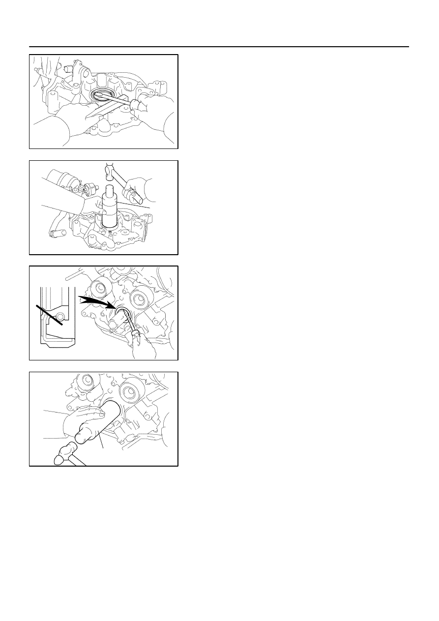
(c)
Inspect the rotors for the side clearance.
Using a feeler gauge and precision straight edge, mea-
sure the clearance between the rotors and precision
straight edge.
Side clearance:
0.030 to 0.090 mm (0.0012 to 0.0035 in.)
Maximum body clearance: 0.09 mm (0.0035 in.)
If the side clearance is greater than maximum, replace the ro-
tors as a set. If necessary, replace the oil pump assembly.
(d)
Inspect the rotor for the body clearance.
Using a feeler gauge, measure the clearance between
the driven rotor and body.
Standard body clearance:
0.250 to 0.325 mm (0.0098 to 0.0128 in.)
Maximum body clearance: 0.325 mm (0.0128 in.)
If the body clearance is greater than maximum, replace the ro-
tors as a set. If necessary, replace the oil pump assembly.
(e)
Remove the drive and drive rotors.
LU0GX–05
A04865
A04866
SST
A04863
Cut Position
A04864
SST
–
LUBRICATION
OIL PUMP
LU–13
2847
REPLACEMENT
REPLACE CRANKSHAFT FRONT OIL SEAL
HINT:
There are 2 methods ((a) and (b)) to replace the oil seal.
(a)
If the oil pump is removed from the cylinder block:
(1)
Using a screwdriver, pry out the oil seal.
(2)
Using SST and a hammer, tap in a new oil seal until
its surface is flush with the oil pump body edge.
SST
09316–60011 (09316–00011)
(3)
Apply MP grease to the oil seal lip.
(b)
If the oil pump is installed to the cylinder block:
(1)
Using a knife, cut off the oil seal lip.
(2)
Using a screwdriver, pry out the oil seal.
NOTICE:
Be careful not to damage the crankshaft. Tape the screw-
driver tip.
(3)
Apply MP grease to a new oil seal lip.
(4)
Using SST and a hammer, tap in the oil seal until its
surface is flush with the oil pump body edge.
SST
09316–60011 (09316–00011)
LU08U–07
B02612
B02611
B02610
LU–14
–
LUBRICATION
OIL PUMP
2848
REASSEMBLY
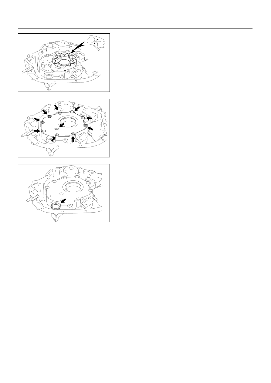
1.
INSTALL DRIVE AND DRIVEN ROTORS
(a)
Place the drive and driven rotors into pump body with the
marks facing the pump body cover side.
(b)
Install the pump body cover with the 10 screws.
Torque: 10 N·m (105 kgf·cm, 7 ft·lbf)
2.
INSTALL RELIEF VALVE
(a)
Insert the relief valve and compression spring into the oil
pump body hole.
(b)
Install the plug.
Torque: 49 N·m (500 kgf·cm, 36 ft·lbf)
Нет комментариевНе стесняйтесь поделиться с нами вашим ценным мнением.
Текст