Toyota Sequoia (2005). Manual — part 133
B17530
Port C
Port B
Port A
Air
B17531
Port C
Port B
Port A
Air
–
DIAGNOSTICS
ENGINE
DI–327
521
9
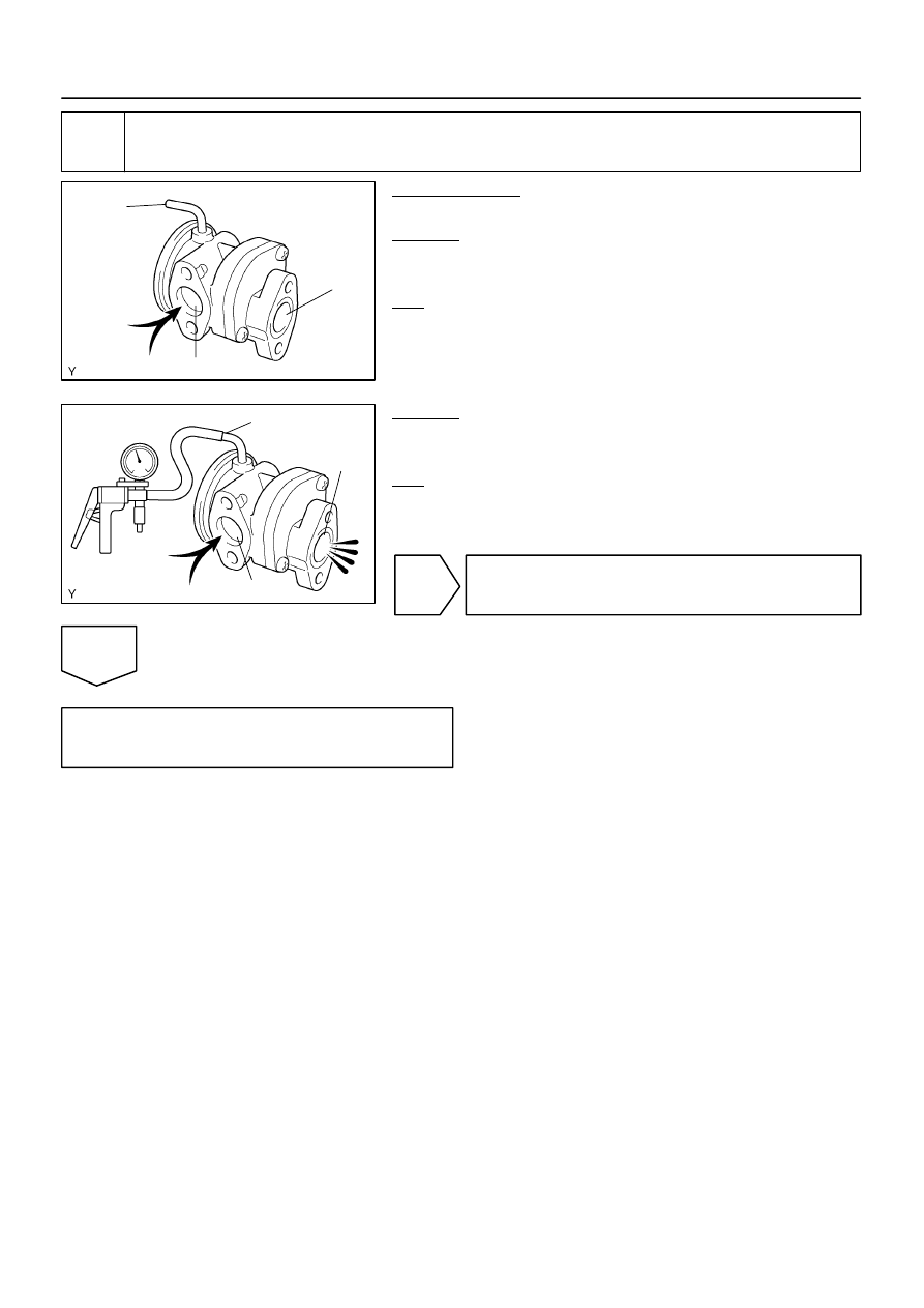
Check air switching valve No.2 operation.
PREPARATION:
Remove the air switching valve No.2.
CHECK:
Blow air into port B and check that air is not discharged from port
C.
OK:
Not discharged from port C
CHECK:
Apply vacuum 30 kPa (225 mmHg) to port A, blow air into port
B and check that air is discharged from port C.
OK:
Discharged from port C
NG
Replace air switching valve No.2.
OK
Check for intermittent problems
(See page
B17516
Air
Port A
B17517
Air
Port A
DI–328
–
DIAGNOSTICS
ENGINE
522
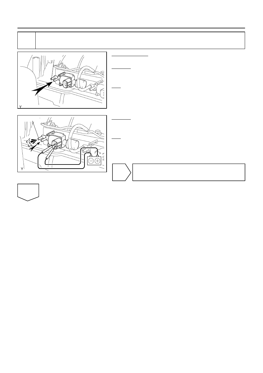
10
Check VSV for air injection control.
PREPARATION:
Disconnect the connector from the VSV for air injection control.
CHECK:
Check that air does not flow from the port as shown in the il-
lustration.
OK:
Does not flow from port A
CHECK:
Apply battery positive across the terminals, check that air flows
from the ports.
OK:
Flows from port A
NG
Replace VSV for air injection control.
OK
B17412
E8
AIV1
AIV2
B17437
V14
VSV Connector
V15
Wire Harness Side:
–
DIAGNOSTICS
ENGINE
DI–329
523
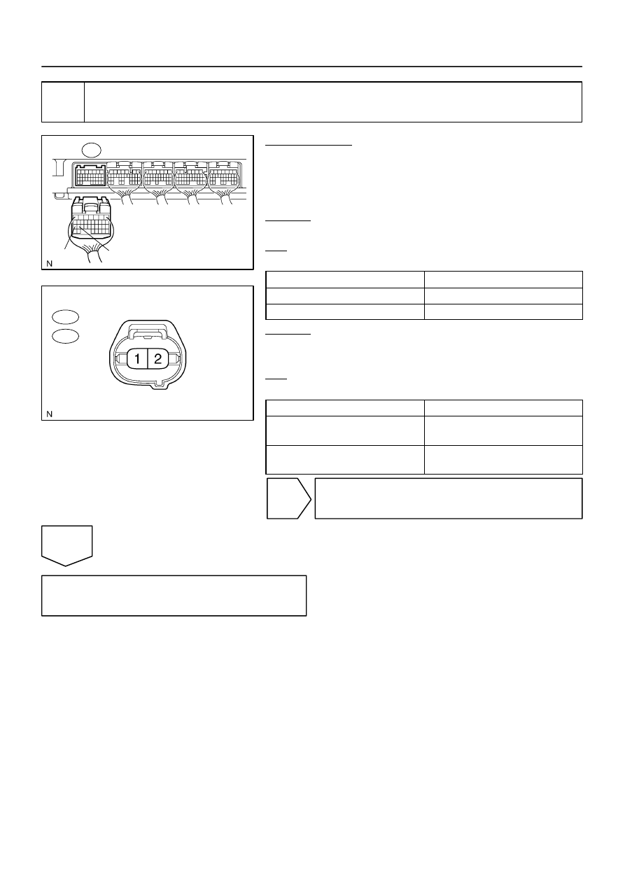
11
Check for open and short circuit in harness and connector between ECM and
VSV for air injection system control
PREPARATION:
(a)
Remove the intake manifold (see page
).
(b)
Disconnect the E8 ECM connector.
(c)
Disconnect the VSV for air injection system control con-
nector.
CHECK:
Measure the resistance between the VSV connector and ECM.
OK:
Standard:
Tester connection
Specified condition
E8–27 (AIV1) – V14–2
Below 1
Ω
E8–26 (AIV1) – V15–2
Below 1
Ω
CHECK:
Measure the resistance between the VSV connector and body
ground.
OK:
Standard:
Tester connection
Specified condition
E8–27 (AIV1) or V14–2 and Body
ground
10 K
Ω
or higher
E8–26 (AIV1) or V15–2 and Body
ground
10 K
Ω
or higher
NG
Repair or replace harness or connector.
OK
Replace ECM (See page
DI–330
–
DIAGNOSTICS
ENGINE
524
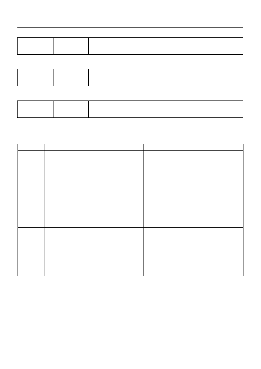
DTC
P1442
Secondary Air Injection System Switching
Valve No.2 Stuck Close Bank 1
DTC
P1445
Secondary Air Injection System Switching
Valve No.2 Stuck Close Bank 2
DTC
P2441
Secondary Air Injection System Switching
Valve Stuck Close Bank 1
CIRCUIT DESCRIPTION
Refer to DTC P0412 on page
.
DTC No.
DTC Detection Condition
Trouble Area
P1442
Air switching valve No.2 (bank 1) stuck close:
No pressure change (decrease) after the ECM sends an open
air switching valve No.2 (bank 1) signal.
(2 trip detection logic)
VSV for air injection control circuit (Bank 1)
Vacuum hose (VSV for air injection control – air switching
valve No.2)
Air injector pipe (Air switching valve No.2 – exhaust manifold)
Air switching valve No.2 (Bank 1)
VSV for air injection control (Bank 1)
ECM
P1445
Air switching valve No.2 (bank 2) stuck close:
No pressure change (decrease) after the ECM sends an open
air switching valve No.2 (bank 2) signal.
(2 trip detection logic)
VSV for air injection control circuit (Bank 2)
Vacuum hose (VSV for air injection control – air switching
valve No.2)
Air injector pipe (Air switching valve No.2 – exhaust manifold)
Air switching valve No.2 (Bank 2)
VSV for air injection control (Bank 2)
ECM
P2441
Air switching valve stuck close:
The pressure sensor does not detect exhaust pulsation when
system operates. (All of air switching valve ON)
This DTC means either of following conditions.
(a) Electromagnetic air switching valve stuck closed.
(b) Both of ”air switching valve No.2 bank 1” and ”air switching
valve No.2 bank 2” stuck closed.
(2 trip detection logic)
Vacuum hoses (Throttle body – VSVs for air injection control)
Air switching valve
Air injector pipe (Air switching valve No.2 – exhaust manifold)
Air injection hose
Air switching valve No.2 (Bank 1 and/or 2)
VSV for air injection control (Bank 1 and/or 2)
Air injection driver
Air injection driver circuit
ECM
MONITOR DESCRIPTION
Refer to DTC P1441, P1444 and P2440 on page
.
DIDMS–01
Нет комментариевНе стесняйтесь поделиться с нами вашим ценным мнением.
Текст