Toyota Sequoia (2005). Manual — part 134
–
DIAGNOSTICS
ENGINE
DI–331
525
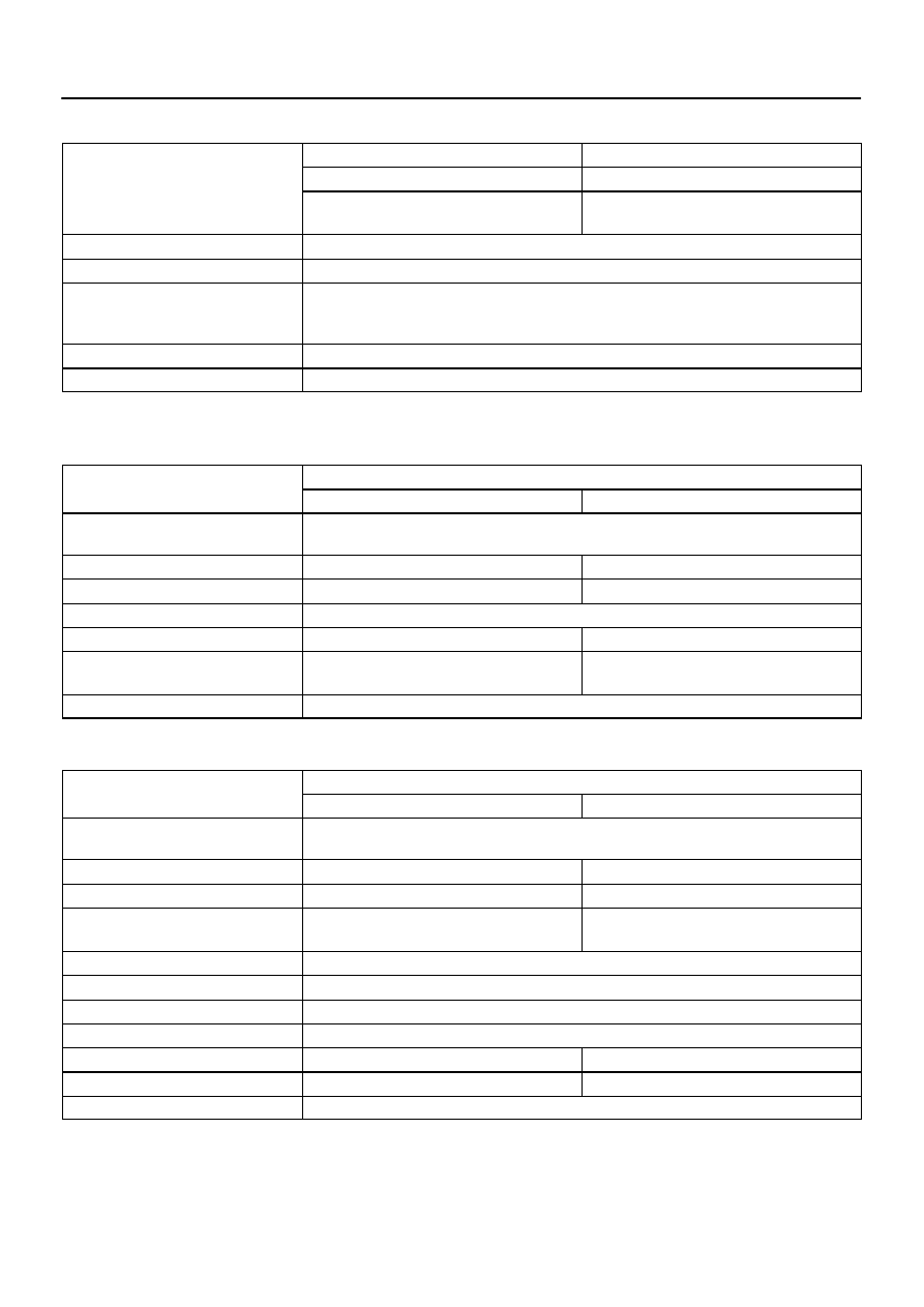
MONITOR STRATEGY
P1442
Air switching valve No. 2 (Bank 1) is stuck closed
Related DTCs
P1445
Air switching valve No. 2 (Bank 2) is stuck closed
Related DTCs
P2441
Air switching valve and air switching valve No.2
are stuck closed
Required sensors/components
Pressure sensor, Air switching valve No. 2 (Bank 1, 2), Electromagnetic air switching valve
Frequency of operation
Continuous
Duration
P1442 (Air switching valve No. 2 (Bank 1) is stuck closed): 20 sec.
P1445 (Air switching valve No. 2 (Bank 2) is stuck closed): 20 sec.
P2441 (Air switching valve is stuck closed): 8 sec.
MIL operation
2 driving cycles
Sequence of operation
None
TYPICAL ENABLING CONDITIONS
P1442, P1445: Air switching valve No. 2 bank 1 and/or bank 2 are stuck closed
It
Specification
Item
Minimum
Maximum
The monitor will run whenever this DTC is
not present
See page
Atmospheric pressure
76 kPa (570 mmHg)
–
Battery voltage
11.5 V
–
Idle
ON
Engine RPM
–
3,750 rpm
Time after secondary air injection out of
operation
10 sec.
–
Air injection pressure sensor fail
Not detected
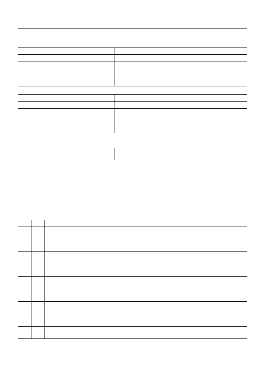
P2441: Electromagnetic air switching valve is stuck closed or air switching valve No. 2 (Bank 1 and
Bank 2) are stuck closed
It
Specification
Item
Minimum
Maximum
The monitor will run whenever this DTC is
not present
See page
Atmospheric pressure
76 kPa (570 mmHg)
–
Battery voltage
11.5 V
–
Time after secondary air injection in op-
eration
6 sec.
–
AIR pump
ON
Air switching valve
ON
Air switching valve No. 2 (Bank 1)
ON
Air switching valve No. 2 (Bank 2)
ON
Engine RPM
–
3,750 rpm
Delay time after engine started
6 sec.
–
Air injection pressure sensor fail
Not detected
DI–332
–
DIAGNOSTICS
ENGINE
526
TYPICAL MALFUNCTION THRESHOLDS
P1442: Air switching valve No. 2 bank 1 is stuck closed
Detection Criteria
Threshold
Both of following conditions are met
Condition 1 and 2
1. Cumulative pressure pulsation
15 kPa (113 mmHg) or more
(when AI ON (Air pump ON, all of air switching valves are ON)
2. Air pressure change
Less than 1 kPa (7.5 mmHg)
(when opening air switching valve No. 2 (Bank 1))
P1445: Air switching valve No. 2 bank 2 is stuck closed
Detection Criteria
Threshold
Both of following conditions are met
Condition 1 and 2
1. Cumulative pressure pulsation
15 kPa (113 mmHg) or more
(when AI ON (Air pump ON, all of air switching valves are ON)
2. Air pressure change
Less than 1 kPa (7.5 mmHg)
(when opening air switching valve No. 2 (Bank 2))
P2441: Electromagnetic air switching valve is stuck closed or air switching valve No. 2 (Bank 1 and
Bank 2) are stuck closed
Cumulative pressure pulsation
Less than 15 kPa (113 mmHg)
(when AI ON (Air pump ON, all of air switching valves are ON)
MONITOR RESULT
Refer to page
for detailed information.
The test value and test limit information are described as shown in the following table. Check the monitor
result and test values after performing the monitor drive pattern (refer to ”Confirmation Monitor”).
MID (Monitor Identification Data) is assigned to each emissions–related component.
TID (Test Identification Data) is assigned to each test value.
Scaling is used to calculate the test value indicated on generic OBD ll scan tools.
Secondary air injection (AIR) system
MID
TID
Scaling
Description of Test Value
Minimum Test Limit
Maximum Test Limit
$71
$E1
Multiply by 0.01
(g/s)
Test value of AIR amount insufficient
Minimum test limit
Maximum test limit
$71
$E2
Multiply by 0.01
(kPa)
Test value of AIR pump stuck ON
Minimum test limit
Maximum test limit
$71
$E3
Multiply by 0.01
(kPa)
Test value of AIR pump stuck OFF
Minimum test limit
Maximum test limit
$71
$E4
Multiply by 0.01
(kPa)
Test value of AIR control valve ON
Minimum test limit
Maximum test limit
$71
$E5
Multiply by 0.01
(kPa)
Test value of AIR control valve OFF
Minimum test limit
Maximum test limit
$71
$E6
Multiply by 0.01
(kPa)
Test value of AIR pressure change for
AIR valve
Minimum test limit
Maximum test limit
$71
$E7
Multiply by 0.01
(kPa)
Test value of AIR pressure change for
AIR VSV bank 1
Minimum test limit
Maximum test limit
$71
$E8
Multiply by 0.01
(kPa)
Test value of AIR pressure change for
AIR VSV bank 2
Minimum test limit
Maximum test limit
$71
$E9
Multiply by 0.01
(kPa)
Test value of AIR pressure pulsation for
AIR VSV when AIR pressure is low
Minimum test limit
Maximum test limit
B17426
–
DIAGNOSTICS
ENGINE
DI–333
527
WIRING DIAGRAM
Refer to DTC P1441, P1444 and P2440 on page
.
INSPECTION PROCEDURE
1
Check any other DTCs output (In addition to secondary air injection system
DTCs).
PREPARATION:
(a)
Connect a hand–held tester to the DLC3.
(b)
Turn the ignition switch to ON and turn the tester ON.
(c)
Select the following menu items: DIAGNOSIS / ENHANCED OBD II / DTC INFO / CURRENT CODES.
CHECK:
(a)
Read DTCs.
RESULT:
Display (DTC Output)
Proceed To
”P1442 and/or P1445” and P2441
A
P1442 and/or P1445
B
”P1442 and/or P1445 and/or P2441” and other DTCs
C
HINT:
If any DTCs other than P1441 and/or P1444 and P2440 are output, troubleshoot those DTCs first.
B
Go to step 6.
C
).
A
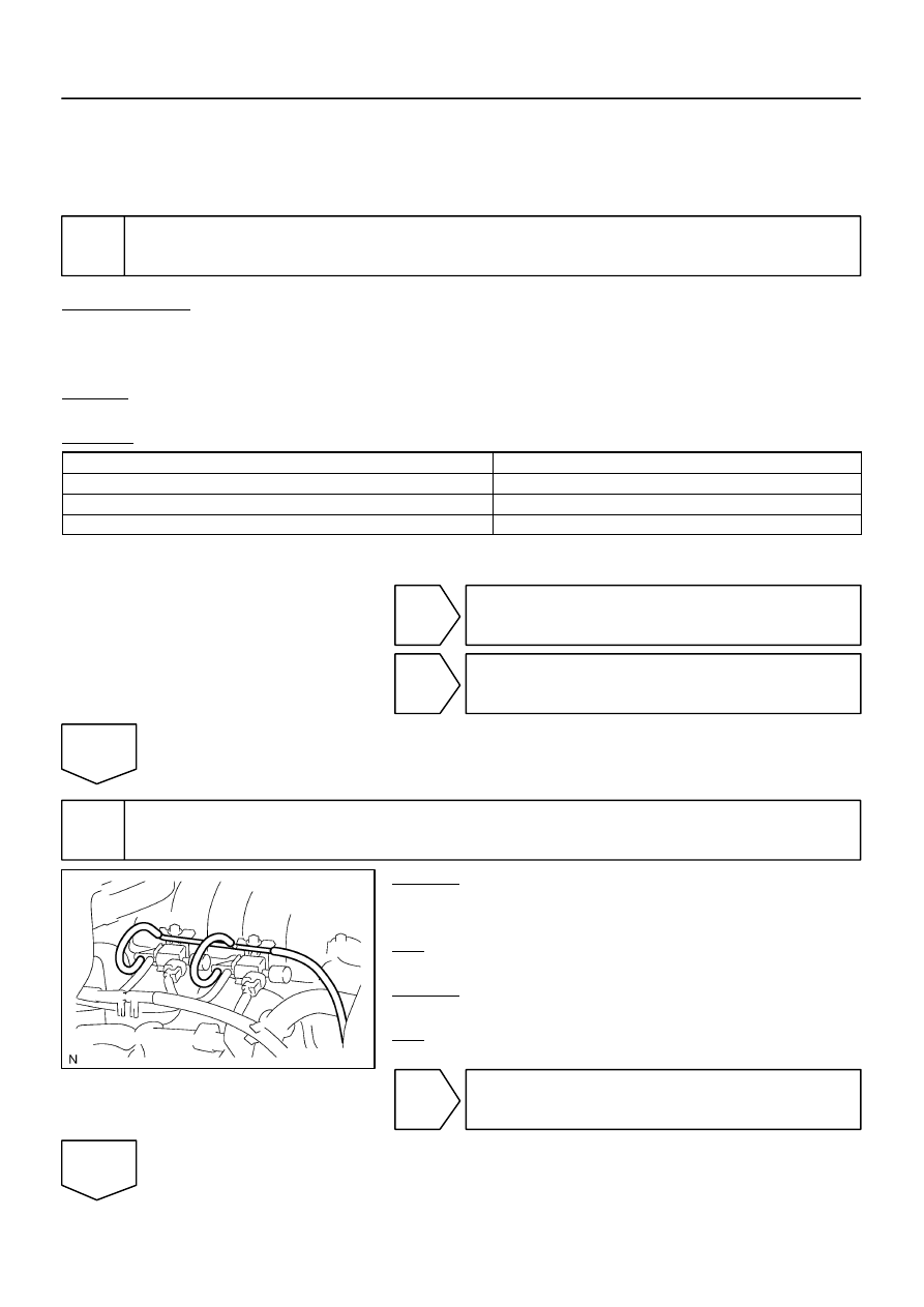
2
Check vacuum hose between throttle body and VSV for air injection control.
CHECK:
(a)
Check that the vacuum hoses between the throttle body
and VSV for air injection control are securely connected.
OK:
The vacuum hoses are securely connected.
CHECK:
(a)
Check the vacuum hoses for blockage or damage.
OK:
The vacuum hoses are no blockages and damage.
NG
Repair or replace vacuum hoses.
OK
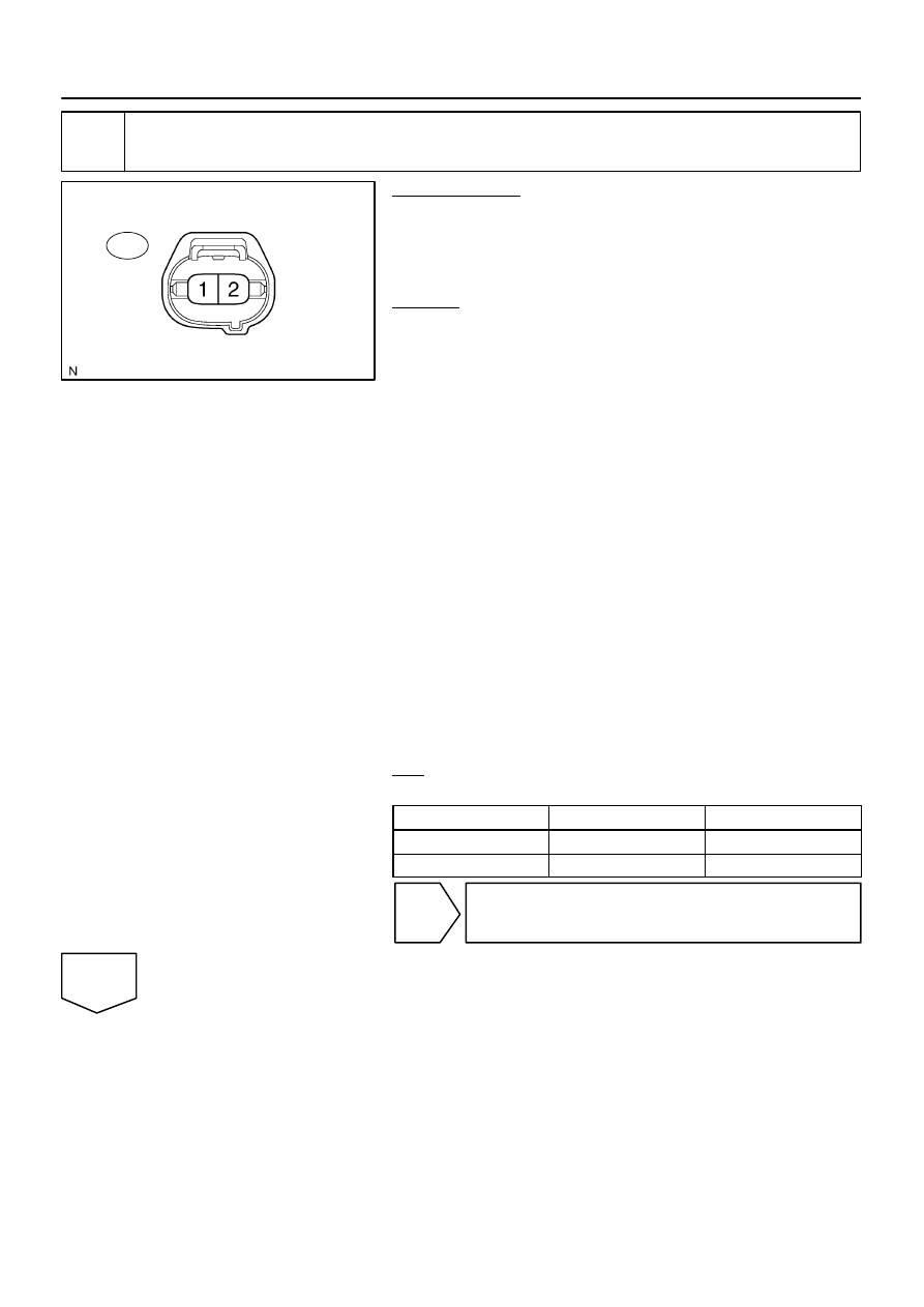
B17440
A46
Air Switching Valve Connector
Wire Harness Side:
DI–334
–
DIAGNOSTICS
ENGINE
528
3
Check voltage between terminal 1 of air switching valve and body ground.
PREPARATION:
(a)
Remove the intake manifold (see page
).
(b)
Disconnect the A46 air switching valve connector.
(c)
Connect the hand–held tester to the DLC3.
(d)
Turn the ignition switch ON and turn the tester ON.
CHECK:
(a)
When the air switching valve is operated using the hand–
held tester, measure voltage between terminal A46–1 of
the air switching valve connector and body ground.
(b)
Select the following menu items: DIAGNOSIS/EN-
HANCED OBD II/SYSTEM CHECK/AIR INJ CHECK/
MANUAL OPERATION/OPERATION 1 and 4
HINT:
OPERATION 1: AP:OFF, EASV:CLOSE, ASV1:CLOSE,
ASV2:CLOSE
OPERATION 4: AP:OFF, EASV:OPEN, ASV1:CLOSE,
ASV2:CLOSE
NOTICE:
This test only allows technicians to operate the AI system
for 5 seconds. Furthermore, the test can be performed 4
times a trip. If the test is repeated, intervals of at least 30
seconds are required between tests.
While the AI system operation using the hand–held tester
is prohibited, the tester displays the prohibition (WAIT or
ERROR). If the ERROR (AI STATUS NG) is displayed on the
tester, stop the engine for 10 minutes and then try again..
OK:
Standard:
Tester operation
Tester Connection
Specified Condition
Operation 4
A46–1 – Body ground
10 V or more
Operation 1
A46–1 – Body ground
Below 1.0 V
NG
Go to step 12.
OK
Нет комментариевНе стесняйтесь поделиться с нами вашим ценным мнением.
Текст