Toyota Sequoia (2005). Manual — part 218

–
DIAGNOSTICS
AUTOMATIC TRANSMISSION
DI–667
861
DTC No.
DTC Detecting Condition
Trouble Area
P2740
(a) and (b) are detected momentarily within 0.5 sec. when
neither P2742 nor P2743 is detected (1–trip detection logic)
(a) ATF temperature sensor No.2 resistance is less than 25
Ω
(
0.046 V
)
(b) ATF temperature sensor No.2 resistance is more than 156
k
Ω (
4.915 V
)
HINT:
Within 0.5 sec. the malfunction switches from (a) to (b) or from
(b) to (a)
Open or short in ATF temperature sensor No.2 circuit
Transmission wire (ATF temperature sensor No.2)
ECM
P2742
ATF temperature sensor No.2 resistance is less than 25
Ω
(
0.046 V
)
for 0.5 sec. or more (1–trip detection logic)
Short in ATF temperature sensor No.2 circuit
Transmission wire (ATF temperature sensor No.2)
ECM
P2743
ATF temperature No.2 sensor resistance is more than 156 k
Ω
(
4.915 V
)
when 15 minutes or more after the engine start
DTC is detected for 0.5 sec. or more (1–trip detection logic)
Open in ATF temperature sensor No.2 circuit
Transmission wire (ATF temperature sensor No.2)
ECM
MONITOR DESCRIPTION
The Automatic Transmission Fluid (ATF) temperature sensor converts ATF temperature to an electrical re-
sistance value. Based on the resistance, the ECM determines the ATF temperature, and the ECM detects
an open or short in the AFT temperature circuit. If the resistance value of the ATF temperature is less than
25
Ω (
0.046 V
)
or more than 156 k
Ω (
4.915 V
)
, the ECM interprets this as a fault in the ATF sensor or wiring.
The ECM will turn on the MIL and store the DTC.
MONITOR STRATEGY
P2740
ATF temperature sensor/Range check (Fluttering)
Related DTCs
P2742
ATF temperature sensor/Range check (Low voltage)
Related DTCs
P2743
ATF temperature sensor/Range check (High voltage)
Required sensors/Components
ATF temperature sensor (TFT sensor)
Frequency of operation
Continuous
Duration
0.5 sec.
MIL operation
Immediate
Sequence of operation
None
TYPICAL ENABLING CONDITIONS
It
Specification
Item
Minimum
Maximum
The monitor will run whenever these
DTCs are not present.
See page
Range check (Fluttering, Low voltage)
The typical enabling condition is not avail-
able.
–
Range check (High voltage)
Time after engine start
15 min. or more
–
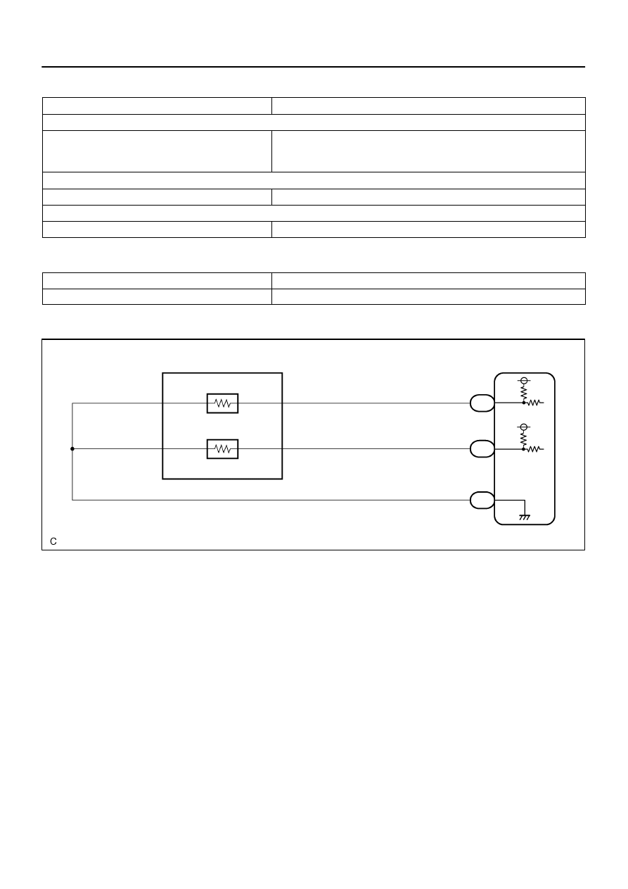
D14157
O
E1 Electronically Controlled
Transmission Solenoid
OT–
O
OT+
L
OT2–
L
OT2+
G–W
G–W
G–W
G
B–L
G–W
2
1
10
9
E7
E7
E8
28
32
24
THO2
THO1
E2
ECM
DI–668
–
DIAGNOSTICS
AUTOMATIC TRANSMISSION
862
TYPICAL MALFUNCTION THRESHOLDS
Detection criteria
Threshold
Range check (Fluttering)
TFT (transmission fluid temperature) sensor voltage
Less than 0.046 V
or
More than 4.915 V
Range check (Low voltage)
TFT (transmission fluid temperature) sensor voltage
Less than 0.046 V
Range check (High voltage)
TFT (transmission fluid temperature) sensor voltage
More than 4.915 V
COMPONENT OPERATING RANGE
Parameter
Standard value
TFT (transmission fluid temperature) sensor
Atmospheric temperature to approx. 130
°
C (266
°
F)
WIRING DIAGRAM

–
DIAGNOSTICS
AUTOMATIC TRANSMISSION
DI–669
863
INSPECTION PROCEDURE
HINT:
According to the DATA LIST displayed by the OBD II scan tool or hand–held tester, you can read the value
of the switch, sensor, actuator and so on without parts removal. Reading the DATA LIST as the first step of
troubleshooting is one method to shorten labor time.
(a)
Warm up the engine.
(b)
Turn the ignition switch off.
(c)
Connect the OBD II scan tool or hand–held tester to the DLC3.
(d)
Turn the ignition switch to the ON position.
(e)
Push the ”ON” button of the OBD II scan tool or the hand–held tester.
(f)
When you use the hand–held tester:
Select the item ”DIAGNOSIS / ENHANCED OBD II / DATA LIST”.
(g)
According to the display on the tester, read the ”DATA LIST”.
Item
Measurement Item/
Range (display)
Normal Condition
AT FLUID TEMP 2
ATF Temp. Sensor Value/
min.: –40
C (–40
F)
max.: 215
C (419
F)
After Stall Test;
Approx. 80
C (176
F)
Equal to ambient temperature when cold soak
HINT:
When DTC P2742 is output and hand–held tester output is 150
C (302
F) or more, there is a short circuit.
When DTC P2743 is output and hand–held tester output is –40
C (–40
F), there is an open circuit.
Measure the resistance between terminal THO2 (OT2) and body ground.
Temperature Displayed
Malfunction
–40
°
C (–40
°
F)
Open circuit
150
°
C (302
°
F) or more
Short circuit

1
15
2
3
4
5
6
7
8
9
10
11
12
13
14
D11994
OT2+
OT2–
Transmission Wire Side:
(Connector Front View):
E1
DI–670
–
DIAGNOSTICS
AUTOMATIC TRANSMISSION
864
1
Inspect transmission wire (ATF temperature sensor No.2)
PREPARATION:
Disconnect the transmission wire connector from the transmis-
sion.
CHECK:
Measure the resistance according to the value(s) in the table
below.
OK:
Tester Connection
Specified Condition
1 (OT2–) – 9 (OT2+)
25
Ω
to 156 k
Ω
1 (OT2–) – Body ground
10 k
Ω
or higher
9 (OT2+) – Body ground
10 k
Ω
or higher
HINT:
If the resistance is out of the specified range with either the ATF
temperature shown in the table below, the driveability of the ve-
hicle may decrease.
ATF Temperature
Specified Condition
20
°
C (68
°
F)
3 to 4 k
Ω
110°
C (230
°
F)
0.22 to 0.28 k
Ω
NG
Repair or replace the transmission wire
(ATF temperature sensor No.2)
(See page
OK
Нет комментариевНе стесняйтесь поделиться с нами вашим ценным мнением.
Текст