Toyota Sequoia (2005). Manual — part 441

–
DIAGNOSTICS
CRUISE CONTROL SYSTEM
DI–1559
1753
2
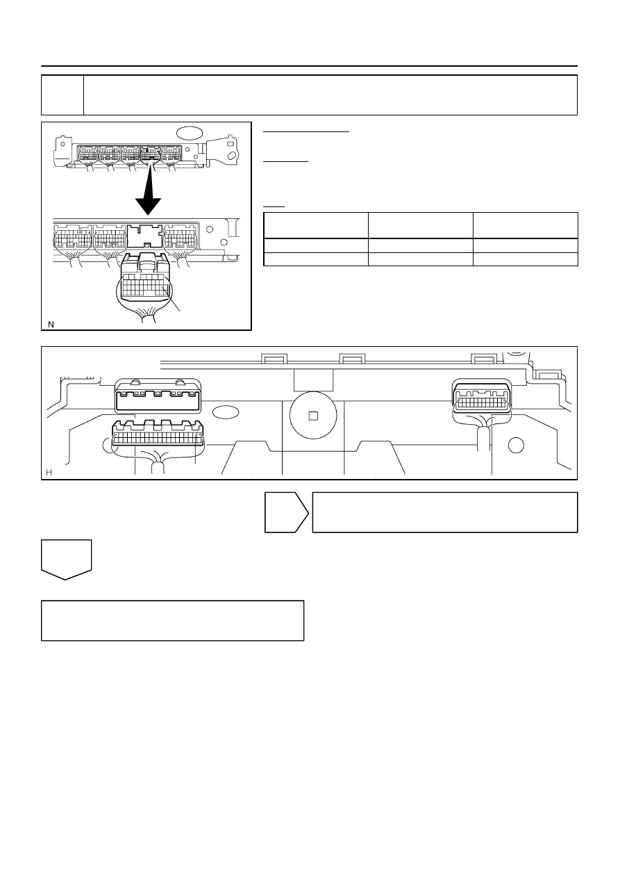
Check combination meter assy.
CHECK:
Check if other functions in the combination meter (speedometer, indicator, etc.) operate normally.
OK:
The other functions operate normally.
NG
Go to combination meter system
(See page
OK
I28461
ECM Wire Harness View:
E5
PI
I27704
C5
Combination Meter
Wire Harness View:
C5–2
DI–1560
–
DIAGNOSTICS
CRUISE CONTROL SYSTEM
1754
3
Check harness and connector (Combination meter assy – ECM).
PREPARATION:
Disconnect the combination meter and ECM connectors.
CHECK:
Measure the resistance according to the value(s) in the table
below.
OK:
Tester connection
(Symbol)
Condition
Specified condition
C5–2 – E5–18 (PI)
Always
Below 1
Ω
C5–2 – Body ground
Always
10 k
Ω
or higher
NG
Repair or replace harness or connector.
OK
Proceed to next circuit inspection shown in
problem symptoms table
(See page
I28463
BR
Spiral Cable Sub–assy
CANCEL
–SET
+RES
ON–OFF
1
ECM
4
CCS
E5
IG4
3
CCS
BR
R–Y
Cruise Control Main Switch
4
5
5
A
A
C9
C9
B
B
ECC
2
EB
14
–
DIAGNOSTICS
CRUISE CONTROL SYSTEM
DI–1561
1755
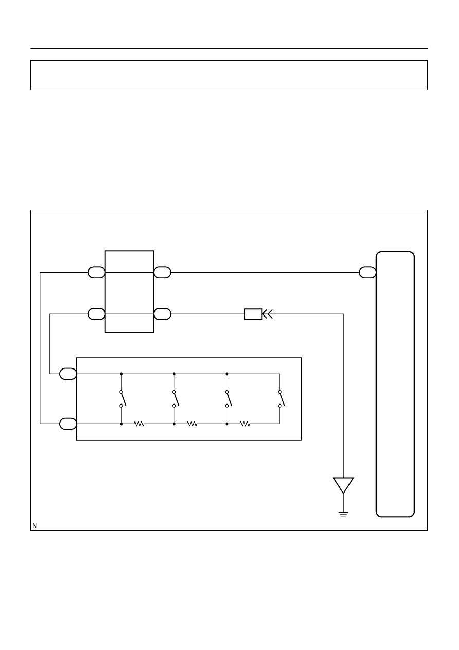
Control Switch Circuit (Cruise Control Switch)
CIRCUIT DESCRIPTION
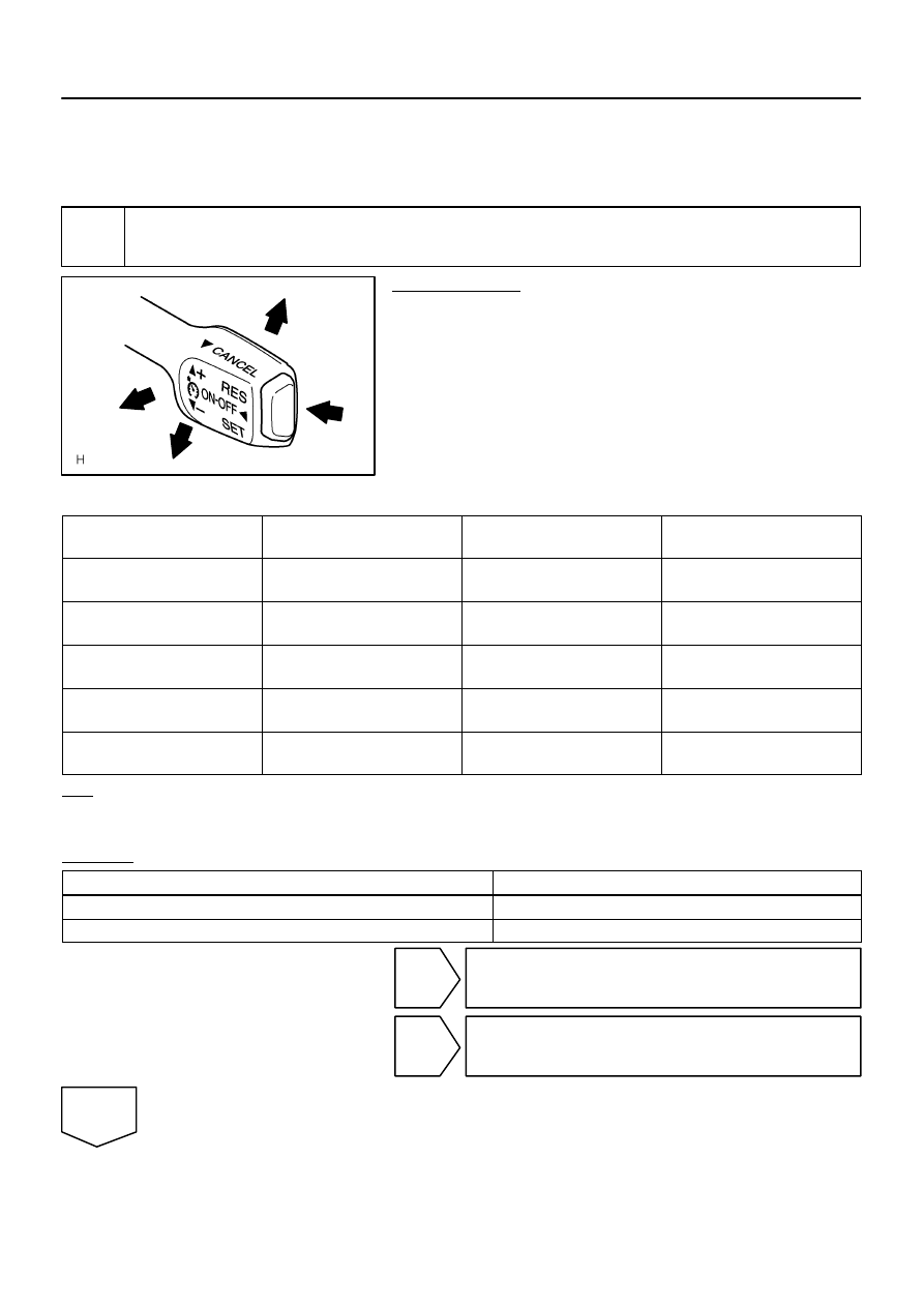
The cruise control main switch operates seven functions: SET, COAST, TAP–DOWN, RESUME, ACCEL,
TAP–UP, and CANCEL. The SET, TAP–DOWN and COAST functions, and the RESUME, ACCEL and TAP–
UP functions are operated with the same switch. The cruise control main switch is an automatic return type
switch which turns on only while operating it in each arrow direction and turns off after releasing it. The inter-
nal contact point of the cruise control main switch is turned on with the switch operation. Then the ECM reads
the CCS terminal voltage value that has been changed by the switch operation to control SET, COAST, RE-
SUME, ACCEL and CANCEL.
WIRING DIAGRAM
DIDF4–01
I24838
ON–OFF
SET/COAST
RES/ACC
CANCEL
DI–1562
–
DIAGNOSTICS
CRUISE CONTROL SYSTEM
1756
INSPECTION PROCEDURE
HINT:
When using the hand–held tester, start the inspection from step 1 and when not using the hand–held tester,
start from step 2.
1
Read value on hand–held tester.
PREPARATION:
(a)
Connect the hand–held tester to the DLC3.
(b)
Turn the ignition switch to the ON position.
(c)
According to the display on the tester, read the ”DATA
LIST”.
CCS (ECM):
Item
Measurement Item
/Display (Range)
Normal Condition
Diagnostic Note
MAIN SW (MAIN)
Main SW signal (Main CPU)
/ON or OFF
ON: Main SW ON (Pushed on)
OFF: Main SW OFF (Pushed off)
–
MAIN SW (SUB)
Main SW signal (Sub CPU)
/ON or OFF
ON: Main SW ON (Pushed on)
OFF: Main SW OFF (Pushed off)
–
CANCEL SW
CANCEL SW signal
/ON or OFF
ON: CANCEL SW ON
OFF: CANCEL SW OFF
–
SET/COAST SW
SET/COAST SW signal
/ON or OFF
ON: SET/COAST SW ON
OFF: SET/COAST OFF
–
RES/ACC SW
RES/ACC SW signal
/ON or OFF
ON: RES/ACC SW ON
OFF: RES/ACC SW OFF
–
OK:
When the cruise control main switch is operated, the normal conditions listed above are shown
on the display.
RESULT:
OK
A
NG (All items are defective.)
B
NG (One to four items are defective.)
C
B
Go to step 2.
C
Replace cruise control main switch.
A
Нет комментариевНе стесняйтесь поделиться с нами вашим ценным мнением.
Текст