Toyota Sequoia (2005). Manual — part 440
I28460
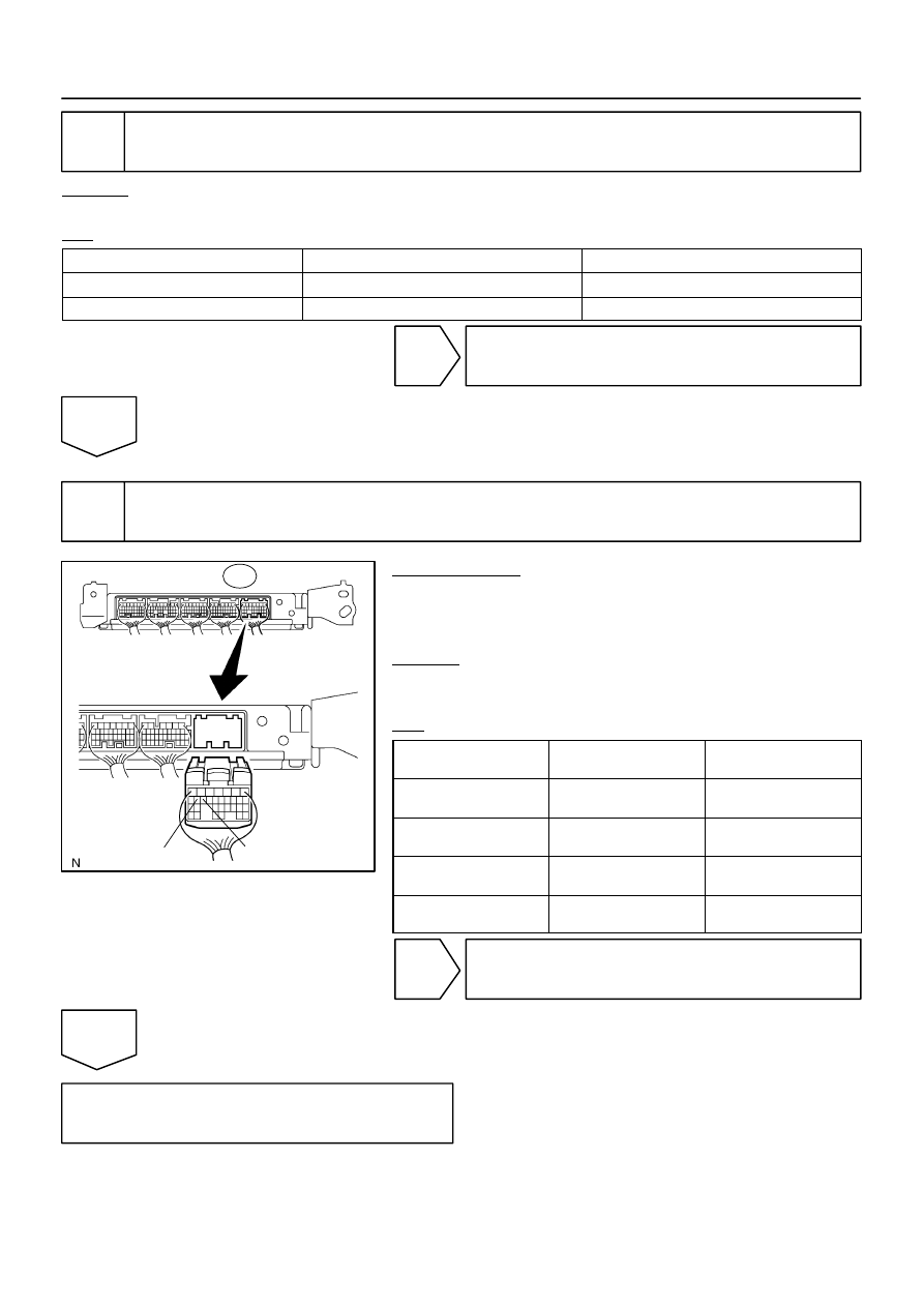
Wire Harness View:
E4
STP
ST1–
–
DIAGNOSTICS
CRUISE CONTROL SYSTEM
DI–1555
1749
4
Check harness and connector (Stop light switch – battery).
CHECK:
Measure the voltage according to the value(s) in the table below.
OK:
Tester connection
Condition
Specified condition
S14–4 – Body ground
Always
10 to 14 V
S14–2 – Body ground
Ignition SW ON
10 to 14 V
NG
Repair or replace harness or connector.
OK
5
Check voltage between terminals STP and ST1– of ECM connector and body
ground.
PREPARATION:
(a)
Reconnect the stop light switch connector.
(b)
Disconnect the ECM connector.
(c)
Turn the ignition switch to the ON position.
CHECK:
Measure the voltage according to the value(s) in the table be-
low.
OK:
Tester connection
(Symbol)
Condition
Specified condition
E4–15 (STP) –
Body ground
Brake pedal depressed
10 to 14 V
E4–15 (STP) –
Body ground
Brake pedal released
Below 1 V
E4–16 (ST1–) –
Body ground
Brake pedal depressed
Below 1 V
E4–16 (ST1–) –
Body ground
Brake pedal released
10 to 14 V
NG
Repair or replace harness or connector.
OK
Replace ECM (See page
DI–1556
–
DIAGNOSTICS
CRUISE CONTROL SYSTEM
1750
DTC
P0607/54 Input signal circuit malfunction
CIRCUIT DESCRIPTION
This DTC indicates the internal abnormalities of the ECM.
DTC No.
Detection Item
Trouble Area
P0607/54
The ECM has a supervisory CPU and a control ECU inside.
When each input STP signal is different for 0.15 sec. or more,
this trouble code is output.
This trouble code is output after 0.4 sec. has passed from the
time the cruise cancel input signal (STP input) is input into the
ECM.
ECM
HINT:
The ECM receives signals from each sensor to control all the functions of the cruise control with the micro-
computer.
When a trouble code is detected, fail safe remains on until the ignition switch is turned off.
INSPECTION PROCEDURE
Replace ECM (See page
).
DIAB7–04
I28462
Combination Meter
Instrument Panel J/B
I18
Ignition SW
Engine Room J/B
PI
ECM
B–O
LG–R
Cruise
W–R
Battery
IG2
B–R
24
3
2
1H
1C
AM2
6
2
1
IGN1
1
C6
7
C5
E5
18
1C
1J
2C
2D
W–R
5
AM2
B
11
B
5
4
F10
FLB
–
DIAGNOSTICS
CRUISE CONTROL SYSTEM
DI–1557
1751
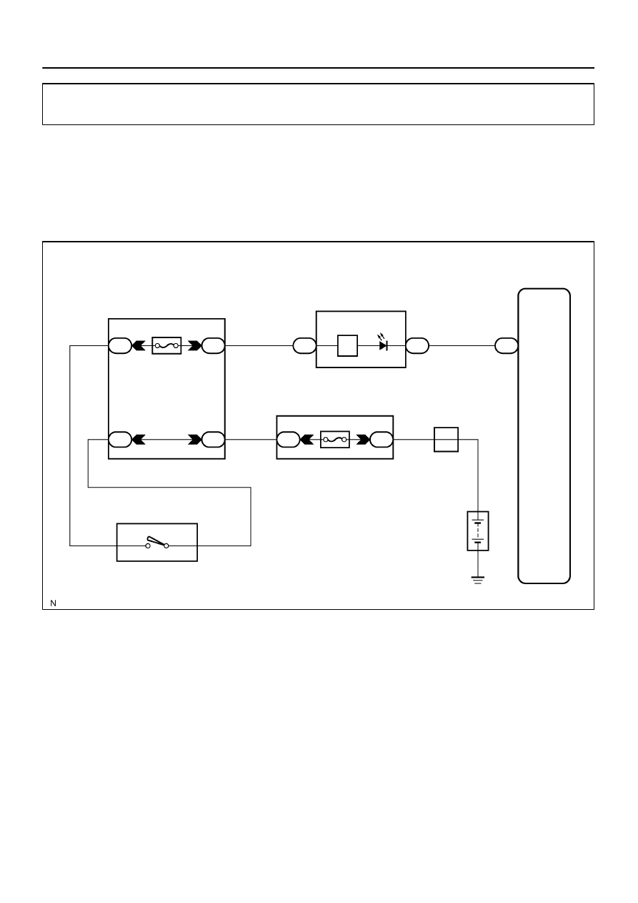
CRUISE main indicator light circuit
CIRCUIT DESCRIPTION
The CRUISE main indicator light comes on while the cruise control system is in operation and blinks when
there are any problems with the system.
DTCs can be read by counting the number of times the CRUISE main indicator light blinks.
WIRING DIAGRAM
DIDF3–01

DI–1558
–
DIAGNOSTICS
CRUISE CONTROL SYSTEM
1752
INSPECTION PROCEDURE
HINT:
When using the hand–held tester, start the inspection from 1 and when not using the hand–held tester, start
from step 2.
1
Read value on hand–held tester.
PREPARATION:
(a)
Connect the hand–held tester to the DLC3.
(b)
Turn the ignition switch to the ON position and turn the hand–held tester main switch on.
(c)
Select the item below in the ”DATA LIST”, and read the display on the hand–held tester.
CHECK:
Check that the CRUISE main indicator light comes on when the cruise main switch is ON, and goes off when
the cruise main switch is OFF.
CCS (ECM):
Item
Measurement Item
/Display (Range)
Normal Condition
Diagnostic Note
CCS INDICATOR
Cruise indicator signal (Main CPU)
/ON or OFF
ON: ”CRUISE main indicator” ON
OFF: ”CRUISE main indicator”
OFF
–
CCS INDICATOR S
Cruise indicator signal (Sub CPU)
/ON or OFF
ON: ”CRUISE main indicator” ON
OFF: ”CRUISE main indicator”
OFF
–
OK:
When the cruise control main switch is operated, the normal conditions listed above are shown
on the display.
NG
Go to step 2.
OK
Proceed to next circuit inspection shown in
problem symptoms table
(See page
Нет комментариевНе стесняйтесь поделиться с нами вашим ценным мнением.
Текст