Toyota Sequoia (2005). Manual — part 174
–
DIAGNOSTICS
ENGINE
DI–491
685
MONITOR RESULT
Refer to page
for detailed information.
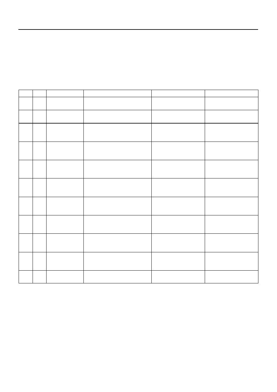
The test value and test limit information are described as shown in the following table. Check the monitor
result and test values after performing the monitor drive pattern (refer to ”Confirmation Monitor”).
MID (Monitor Identification Data) is assigned to each emissions–related component.
TID (Test Identification Data) is assigned to each test value.
Scaling is used to calculate the test value indicated on generic OBD ll scan tools.
EVAP–Key–off monitor
MID
TID
Scaling
Description of Test Value
Minimum Test Limit
Maximum Test Limit
$3D
$C9
Multiply by 0.01
(kPa)
Test value for small leak (P0456):
Refer to pressure D*.
Minimum test limit for small
leak
Maximum test limit for small
leak
$3D
$CA
Multiply by 0.01
(kPa)
Test value for gross leak (P0455):
Refer to pressure E*.
Minimum test limit for gross
leak
Maximum test limit for gross
leak
$3D
$CB
Multiply by 0.01
(kPa)
Test value for vacuum pump stuck OFF
(P2401):
Refer to pressure A*.
Minimum test limit for vacuum
pump stuck OFF
Maximum test limit for vacuum
pump stuck OFF
$3D
$CD
Multiply by 0.01
(kPa)
Test value for vacuum pump stuck ON
(P2402):
Refer to pressure A*.
Minimum test limit for vacuum
pump stuck ON
Maximum test limit for vacuum
pump stuck ON
$3D
$CE
Multiply by 0.01
(kPa)
Test value for vent valve stuck OFF
(vent) (P2420):
Refer to pressure C*.
Minimum test limit for vent
valve stuck ON
Maximum test limit for vent
valve stuck ON
$3D
$CF
Multiply by 0.01
(kPa)
Test value for vent valve stuck ON
(closed) (P2419):
Refer to pressure A*.
Minimum test limit for vent
valve stuck OFF
Maximum test limit for vent
valve stuck OFF
$3D
$D0
Multiply by 0.01
(kPa)
Test value for 0.02 inch orifice low flow
(P043E):
Refer to pressure B*.
Minimum test limit for 0.02
inch orifice low flow
Maximum test limit for 0.02
inch orifice low flow
$3D
$D1
Multiply by 0.01
(kPa)
Test value for 0.02 inch orifice high flow
(P043F):
Refer to pressure A*.
Minimum test limit for 0.02
inch orifice high flow
Maximum test limit for 0.02
inch orifice high flow
$3D
$D4
Multiply by 0.01
(kPa)
Test value for purge VSV stuck close
(P0441):
Refer to pressure F*.
Minimum test limit for purge
VSV stuck close
Maximum test limit for purge
VSV stuck close
$3D
$D5
Multiply by 0.01
(kPa)
Test value for purge VSV stuck open
(P0441):
Refer to pressure E*.
Minimum test limit for purge
VSV stuck open
Maximum test limit for purge
VSV stuck open
$3D
$D7
Multiply by 0.01
(kPa)
Test value for purge flow (P0441):
Refer to pressure G*.
Minimum test limit for purge
flow
Maximum test limit for purge
flow
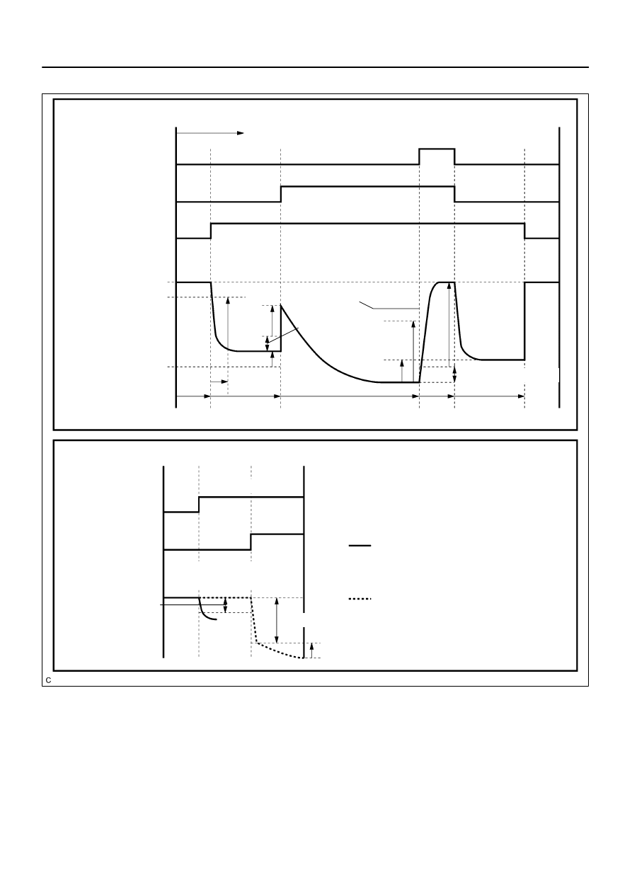
* Pressure A to G are indicated as shown in the diagram below.
A23517
Key–off Monitor
Purge VSV
Vent Valve
Atmosphere (0 kPa)
Criterion 1 (–1.2 kPa)
Criterion 5 (–4.3 kPa)
Elapsed Time (Seconds)
10
4
EVAP Pressure
(Reference)
Pump
Monitor Start
ON (Open)
ON (Close)
ON
A
B
C
60
D
G
Within 720
Criterion 2 (Criterion 4 x 0.2)
Criterion 3 (0.3 kPa)
Criterion 4
E
F
Criterion 6 (0.3 kPa)
10
60
Purge Flow Monitor
Sequence
Purge VSV
Vent Valve
Criterion 7 (0.1 kPa)
EVAP Pressure
(Reference)
Criterion 8 (1kPa)
If pressure change in sequence 1 is
greater than criterion 7, purge flow moni-
tor is completed (functioning normally).
ON (Close)
1
2
ON (Open)
If pressure change in sequence 1 is
smaller than criterion 7, sequence 2 is
run.
If pressure change in sequence 2 is
smaller than criterion 8, purge flow is in-
sufficient.
DI–492
–
DIAGNOSTICS
ENGINE
686

–
DIAGNOSTICS
ENGINE
DI–493
687
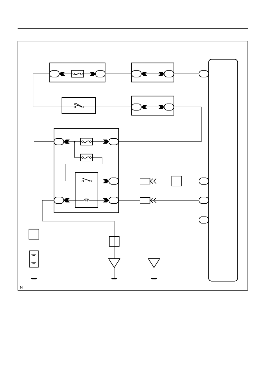
ECM Power Source Circuit
CIRCUIT DESCRIPTION
When the ignition switch is turned ON, battery positive voltage is applied to terminal IGSW of the ECM and
the EFI relay control circuit in the ECM sends a signal to terminal MREL of the ECM switching on the EFI
relay.
This signal causes current to flow to the coil, closing the contacts of the EFI relay and supplying power to
terminal +B of the ECM.
DID8K–01
A23555
F10
Fusible
Link
Block
9
+B
Battery
E1
1
8
1
E4
E6
BR
4D
B–R
6
7
I18 Ignition SW
2
W–R
1C
1E
1C
2
1
3
B
IG2
IA4
B–W
ECM
Engine Room J/B
EFI Relay
1
D
IGSW
MREL
E4
E4
17
IGN1
4E
Instrument Panel J/B
Sub J/B No. 4
5
AM2
Instrument Panel J/B
1
1
6
AM2
1J
2D
2F
2C
2H
5
3
2
IA4
J/C
5
4
B
14
12
2
J16
A
EB
ED
D
J5
J/C
W–B
2H
2
B–R
B–W
B–R
B–R
EFI No. 1
W–R
B–O
B–O
DI–494
–
DIAGNOSTICS
ENGINE
688
WIRING DIAGRAM
Нет комментариевНе стесняйтесь поделиться с нами вашим ценным мнением.
Текст