Toyota Sequoia (2005). Manual — part 172
A23446
L5
A23508
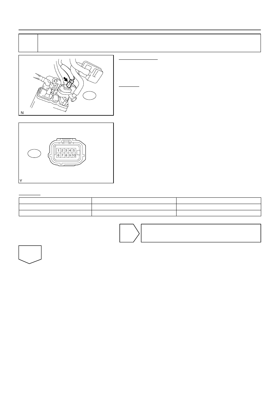
Wire Harness Side:
Canister Connector
Front View
L5
–
DIAGNOSTICS
ENGINE
DI–483
677
21
Inspect pump module power source circuit.
PREPARATION:
(a)
Turn the ignition switch to OFF.
(b)
Disconnect the L5 canister connector.
(c)
Turn the ignition switch to ON.
CHECK:
Measure the voltage between terminal 9 of the canister connec-
tor and the body ground.
RESULT:
Test Results
Suspected Trouble Areas
Proceed To
Between 9 V and 14 V
Normal
A
Between 0 V and 3 V
Power source wire harness of vent valve
B
B
Go to step 32.
A
B17423
8 (–)
9 (+)
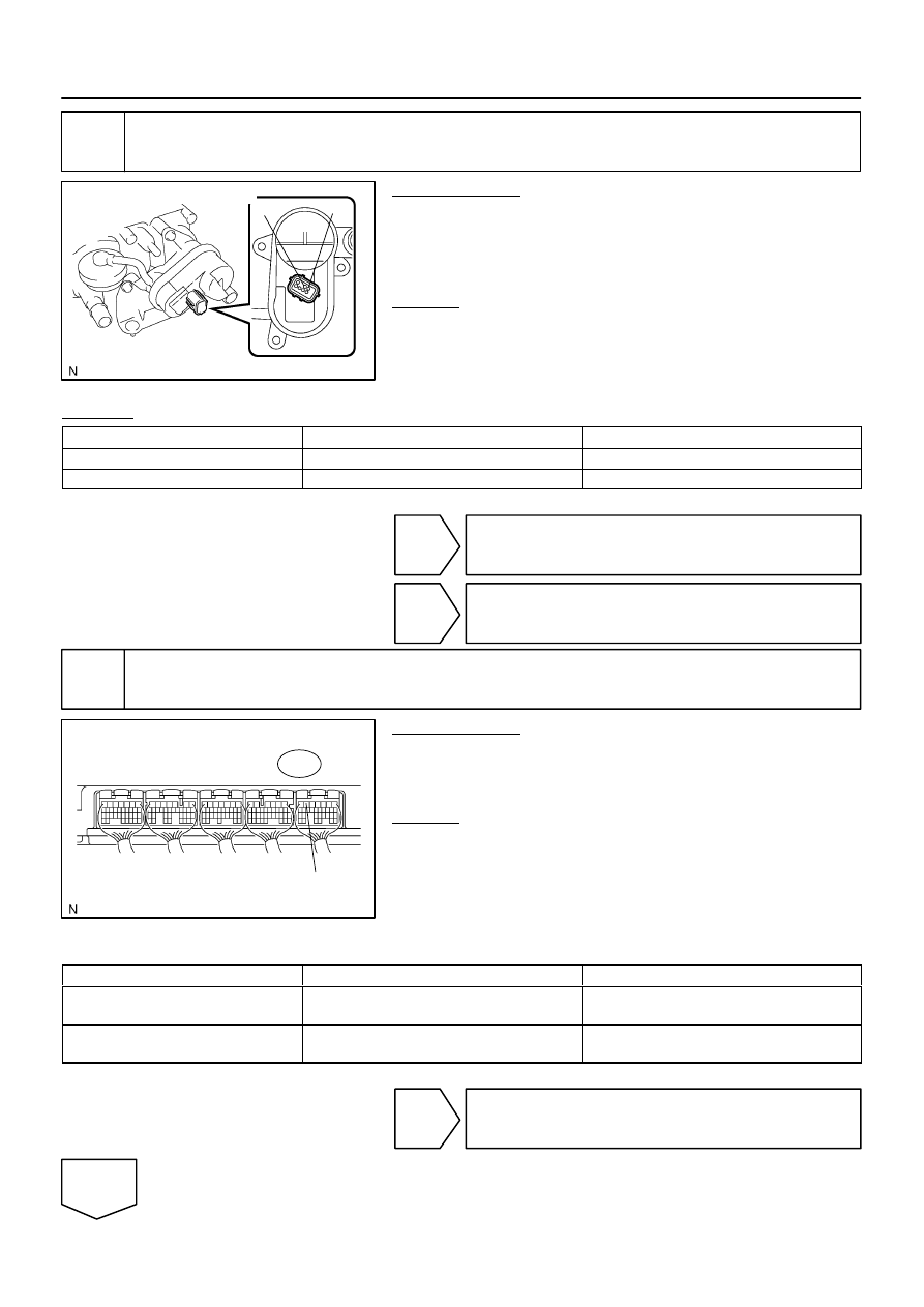
Charcoal Canister Assy:
B17411
MPMP
E4
DI–484
–
DIAGNOSTICS
ENGINE
678
22
Inspect vent valve operation of pump module.
PREPARATION:
(a)
Disconnect the L5 canister connector.
(b)
Turn the ignition switch to OFF.
(c)
Apply the battery voltage to terminals 9 and 8 of the pump
module.
CHECK:
Touch the pump module to confirm the vent valve operation.
RESULT:
Test Results
Suspected Trouble Areas
Proceed To
Operating
Wire harness between vent valve and ECM
A
Not operating
Vent valve
B
A
Go to step 32.
B
Go to step 30.
23
Perform active test for vacuum pump.
PREPARATION:
On the hand–held tester, select the following menu items:
DIAGNOSIS / ENHANCED OBD II / ACTIVE TEST / VACUUM
PUMP (ALONE).
CHECK:
Measure the voltage between terminal MPMP of the ECM con-
nector and the body ground when the vacuum pump is turned
ON and OFF using the tester.
Result:
Tests Results
Suspected Trouble Areas
Proceed To
Between 0 V and 3 V when OFF
Between 9 V and 14 V when ON
ECM normal
A
Between 9 V and 14 V when OFF
Between 0 V and 3 V when ON
ECM
B
B
Go to step 35.
A
A23446
L5
A23508
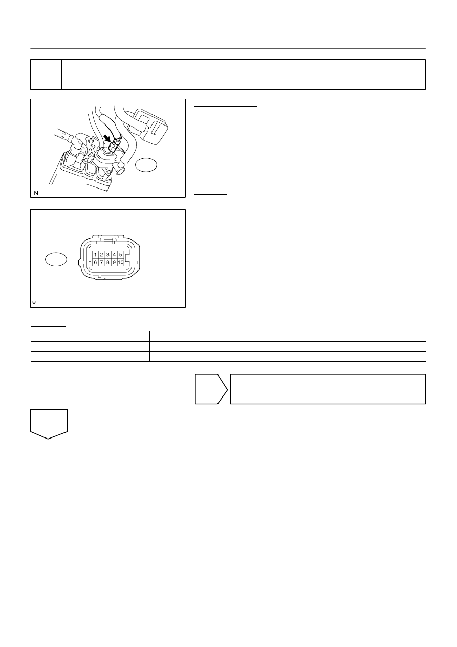
Wire Harness Side:
Canister Connector
Front View
L5
–
DIAGNOSTICS
ENGINE
DI–485
679
24
Check for open and short circuit in harness and connecter between pump mod-
ule and ECM.
PREPARATION:
(a)
Turn the ignition switch to OFF.
(b)
Disconnect the L5 canister connector.
(c)
Turn the ignition switch to ON.
(d)
On the hand–held tester, select the following menu
items:DIAGNOSIS / ENHANCED OBD II / ACTIVE TEST
/ VACUUM PUMP (ALONE).
(e)
Turn the vacuum pump ON.
CHECK:
Measure the voltage between terminal 1 of the canister connec-
tor and the body ground.
RESULT:
Test Results
Suspected Trouble Areas
Proceed To
Between 9 V and 14 V
Normal
A
Between 0 V and 3 V
Wire harness between ECM and vacuum pump
B
B
Go to step 32.
A
A23508
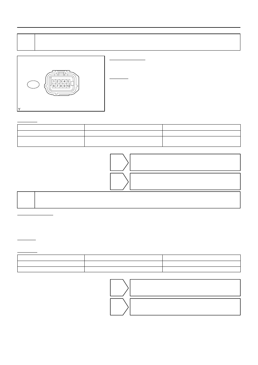
Wire Harness Side:
Canister Connector
Front View
L5
DI–486
–
DIAGNOSTICS
ENGINE
680
25
Check for open and short in harness and connector between pump module and
ECM.
PREPARATION:
(a)
Disconnect the L5 canister connector.
(b)
Turn the ignition switch to OFF.
CHECK:
Check the resistance between terminal 6 of the canister con-
nector and the body ground.
RESULT:
Test Results
Suspected Trouble Areas
Proceed To
Below 1
Ω
Vacuum pump
A
10 k
Ω
or more
Wire harness between vacuum pump and body
ground
B
A
Go to step 30.
B
Go to step 32.
26
Inspect throttle body.
PREPARATION:
(a)
Stop the engine.
(b)
Disconnect the EVAP hose from the throttle body.
(c)
Start the engine.
CHECK:
(a)
Use your finger to confirm that the port of the throttle body has suction.
RESULT:
Test Results
Suspected Trouble Areas
Proceed To
Suction applied
EVAP hose between throttle body and purge VSV
A
No suction
Throttle body
B
A
Go to step 33.
B
Go to step 34.
Нет комментариевНе стесняйтесь поделиться с нами вашим ценным мнением.
Текст