Toyota Sequoia (2005). Manual — part 432
I28701
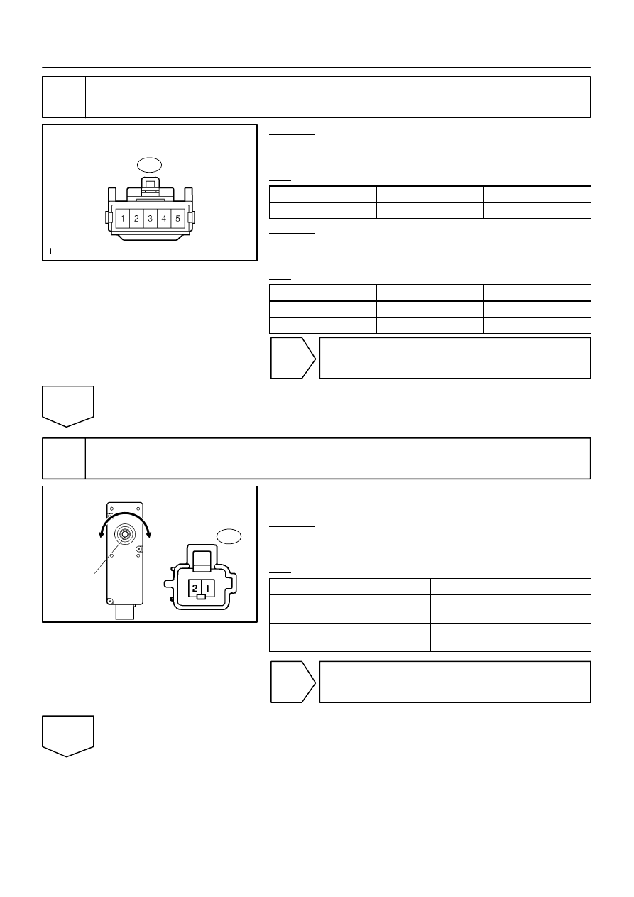
Wire Harness Side:
Lumbar Support Control Switch
L4
I28702
Lumbar Support Control Motor
Clockwise
Counter-
clockwise
Driving Axis
L3
–
DIAGNOSTICS
POWER SEAT CONTROL SYSTEM (w/ Driving Position
Memory)
DI–1523
1717
3
Check harness and connector (Power source).
CHECK:
Measure the voltage of each terminal of the wire harness side
connectors.
OK:
Tester Connection
Condition
Specified Condition
L4–3 – Body ground
Always
10 to 14 V
CHECK:
Measure the resistance of each terminal, as shown in the il-
lustration and table.
OK:
Tester Connection
Condition
Specified Condition
L4–2 – Body ground
Always
Below 1
Ω
L4–5 – Body ground
Always
Below 1
Ω
NG
Repair or replace harness or connector.
OK
4
Inspect lumbar support control motor.
PREPARATION:
Remove the lumbar support control motor (See page
CHECK:
Check that the motor rotates smoothly when the battery is con-
nected to the lumbar support control motor connector terminals.
OK:
Measurement Condition
Operational Direction
Battery positive (+)
→
1
Battery negative (–)
→
2
Clockwise
Battery positive (+)
→
2
Battery negative (–)
→
1
Counterclockwise
NG
Replace lumbar support control motor
(See page
OK
I28701
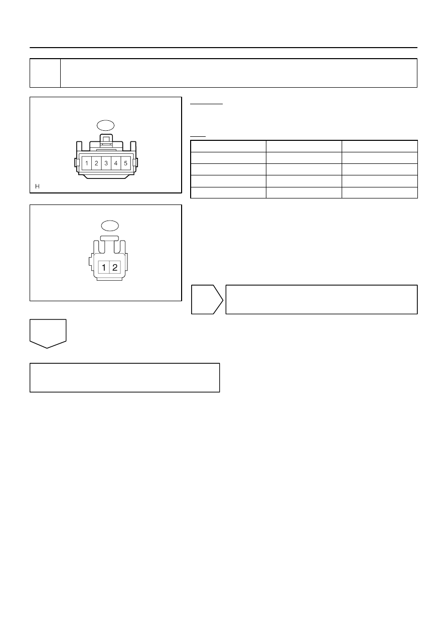
Wire Harness Side:
Lumbar Support Control Switch
L4
I28555
Wire Harness Side:
Lumbar Support
Control Motor
L3
DI–1524
–
DIAGNOSTICS
POWER SEAT CONTROL SYSTEM (w/ Driving Position
Memory)
1718
5
Check harness and connector (Lumbar support control switch – lumbar support
control motor).
CHECK:
Measure the resistance of each terminal, as shown in the il-
lustration and table.
OK:
Tester Connection
Condition
Specified Condition
L4–1 – L3–2
Always
Below 1
Ω
L4–4 – L3–1
Always
Below 1
Ω
L4–1 – Body ground
Always
10 k
Ω
or higher
L4–4 – Body ground
Always
10 k
Ω
or higher
NG
Repair or replace harness or connector.
OK
Proceed to next circuit inspection shown in
problem symptoms table (See page
).
I28449
Position Control
ECU & Switch
SLD–
SLD+
FRV–
FRV+
LFT–
LFT+
RCL–
RCL+
2
1
2
1
2
1
2
1
3
M7
M7
M7
M7
M7
M7
M7
M7
2
4
6
9
7
10
8
BR
P14
Power Seat Motor
(Driver’s Seat Front Vertical Control)
P16
Power Seat Motor
(Driver’s Seat Reclining Control)
P
V
W
B
G
Y
L
P15
Power Seat Motor
(Driver’s Seat Rear Vertical Control)
P17
Power Seat Motor
(Driver’s Seat Slide Control)
–
DIAGNOSTICS
POWER SEAT CONTROL SYSTEM (w/ Driving Position
Memory)
DI–1525
1719
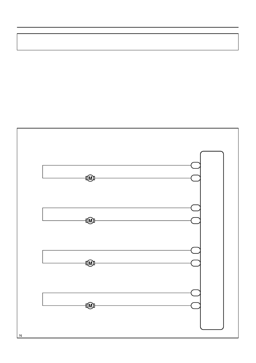
Power seat motor circuit
CIRCUIT DESCRIPTION
When the power seat control switch is operated, a command signal is sent to the position control ECU. The
position control ECU then controls the appropriate seat motor as needed. This memory system does not use
a seat position sensor. The seat position is detected by counting pulses that are output when the motor turns.
If there is no pulse output from the motor, the motor will stop operating. The ECU is designed so that a mal-
function of the seat memory system will not interfere with manual seat control.
When the position control ECU switch assy detects the low motor speed or abnormal activity, the system
stops the motor. When the motor continuously operates for 120 seconds or more, the system will stop the
motor until the switch is turned off.
WIRING DIAGRAM
DIDEB–01
I07253
1
2
1
2
DI–1526
–
DIAGNOSTICS
POWER SEAT CONTROL SYSTEM (w/ Driving Position
Memory)
1720
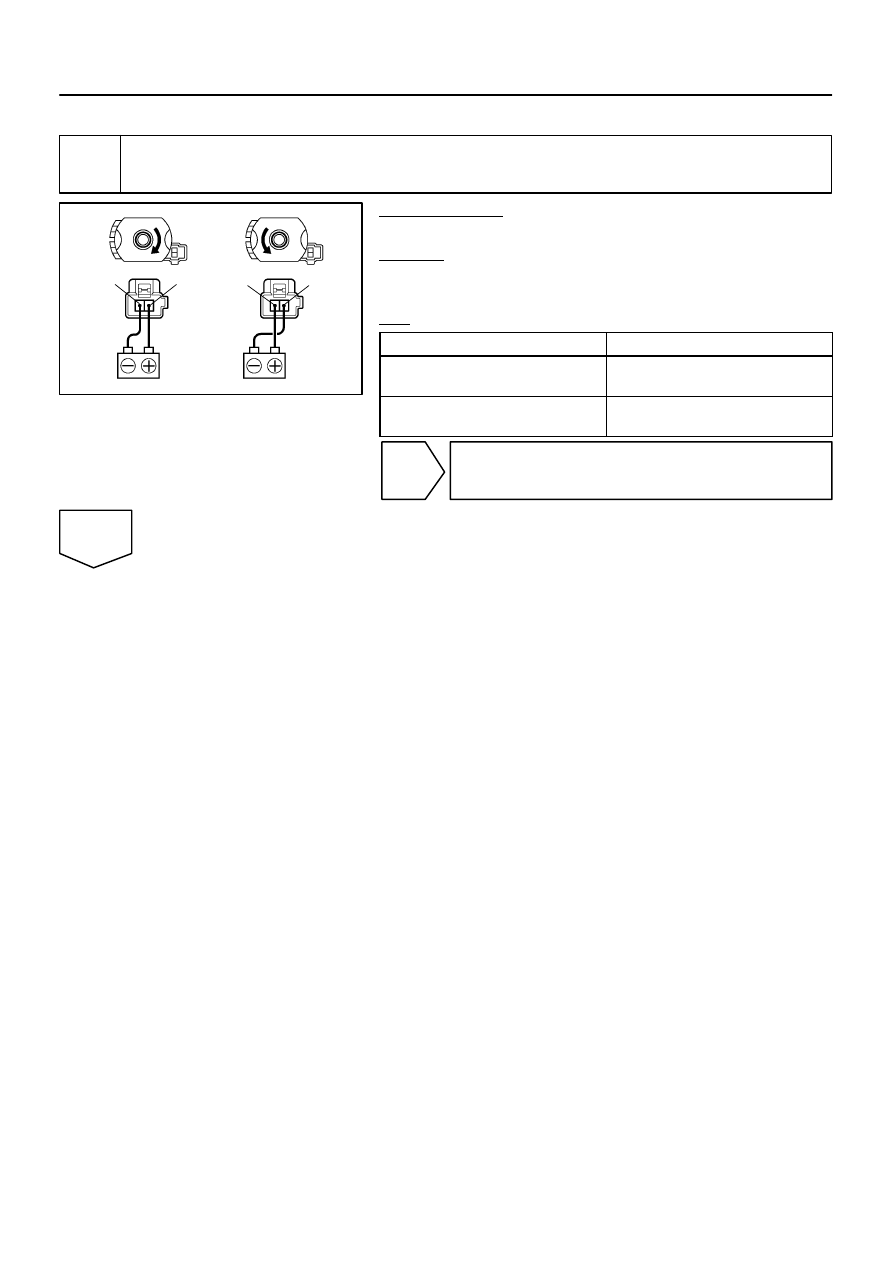
INSPECTION PROCEDURE
1
Inspect power seat motor assy.
PREPARATION:
Remove the power seat motor (See page
).
CHECK:
Check that the motor rotates smoothly when the battery is con-
nected to the connector terminal.
OK:
Tester Connection
Specified Condition
Battery positive voltage – 1
Battery negative voltage – 2
Counterclockwise
Battery positive voltage – 2
Battery negative voltage – 1
Clockwise
NG
Replace power seat motor (See page
OK
Нет комментариевНе стесняйтесь поделиться с нами вашим ценным мнением.
Текст