Toyota Sequoia (2005). Manual — part 433
I28704
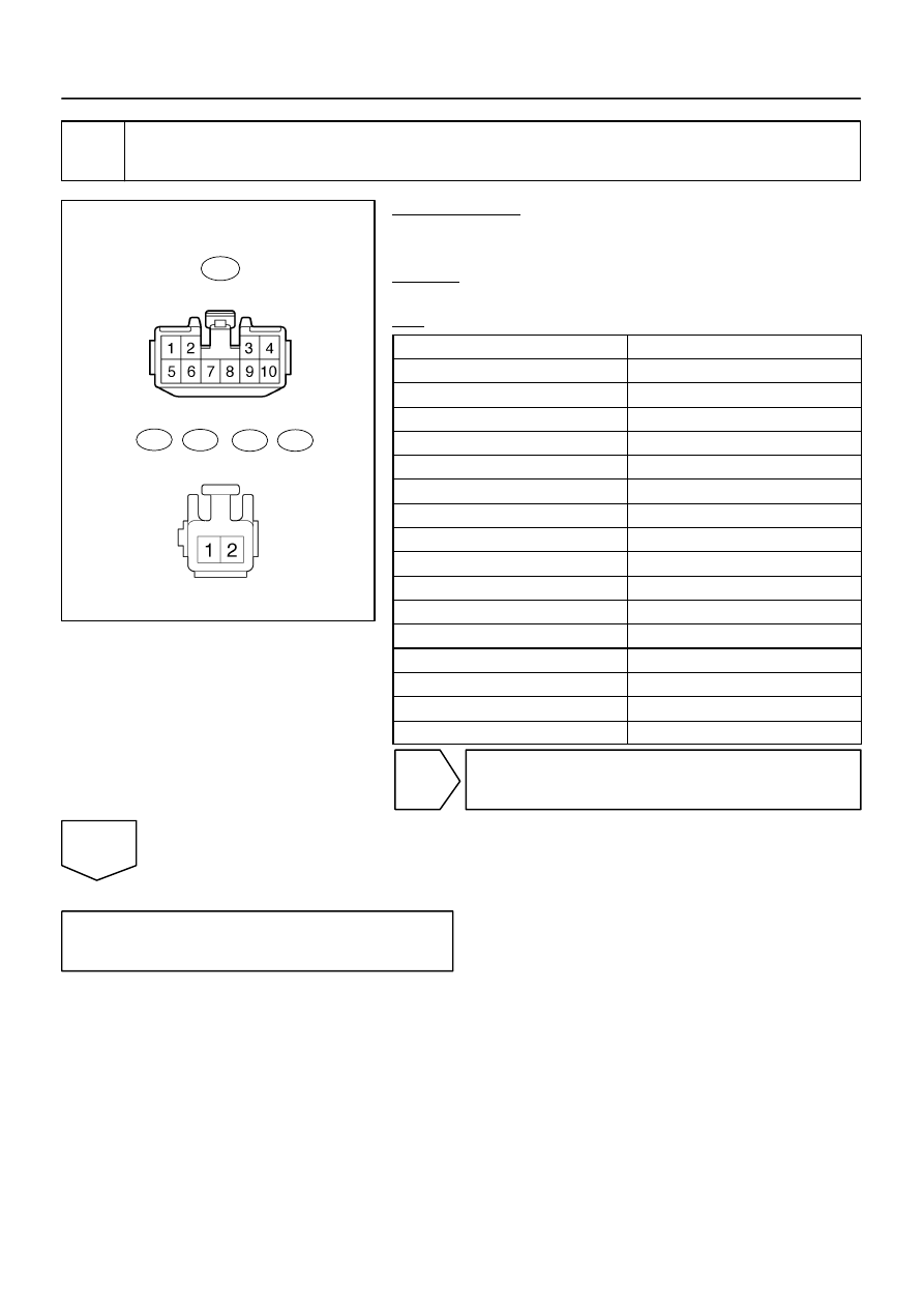
Wire Harness Side:
Position Control ECU & Switch Assy
Power Seat Motor Assy
P14
P16
P15
P17
M7
–
DIAGNOSTICS
POWER SEAT CONTROL SYSTEM (w/ Driving Position
Memory)
DI–1527
1721
2
Check harness and connector (Position control ECU & switch assy – power seat
motor assy).
PREPARATION:
Disconnect the M7 ECU and P14, P15, P16 and P17 motor con-
nectors.
CHECK:
Measure the resistance of the wire harness side connectors.
OK:
Tester Connection
Specified Condition
M7–2 – P17–1
Below 1
Ω
M7–3 – P17–2
Below 1
Ω
M7–4 – P14–2
Below 1
Ω
M7–6 – P14–1
Below 1
Ω
M7–7 – P15–2
Below 1
Ω
M7–9 – P15–1
Below 1
Ω
M7–8 – P16–2
Below 1
Ω
M7–10 – P16–1
Below 1
Ω
M7–2 – Body ground
10 k
Ω
or higher
M7–3 – Body ground
10 k
Ω
or higher
M7–4 – Body ground
10 k
Ω
or higher
M7–6 – Body ground
10 k
Ω
or higher
M7–7 – Body ground
10 k
Ω
or higher
M7–8 – Body ground
10 k
Ω
or higher
M7–9 – Body ground
10 k
Ω
or higher
M7–10 – Body ground
10 k
Ω
or higher
NG
Repair or replace harness or connector.
OK
Proceed to next circuit inspection shown in
problem symptoms table
(See page
I28451
Battery
J/C
I18
Ignition SW
1
2
AM1
IG1
5
W
B
F10
FL Block
ALT
8
1L
1C
Instrument Panel J/B
7
J52
J51
2
1
AM1
6
1C
4
1
7
8
L–Y
1
MPX1
M6
W
W
C5
C5
34
30
Combination Meter
Position Control
ECU & Switch
P
L–Y
L–R
L–R
C
C
PL
RB
6
2
P1
Park/Neutral
Position Switch
B–Y
W–L
GAUGE
IPO
IG4
9
BEAN
1D
DI–1528
–
DIAGNOSTICS
POWER SEAT CONTROL SYSTEM (w/ Driving Position
Memory)
1722
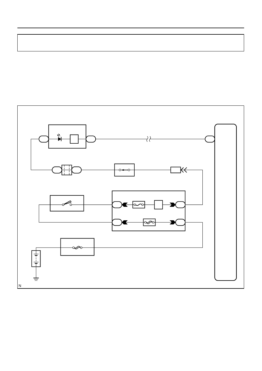
Park/neutral position switch circuit
CIRCUIT DESCRIPTION
The power seat memory system operates only when the ignition switch is in the ON position and the park/
neutral position is in the P (park) position.
The position control ECU & switch assy detects the P position, via multiplex communication, through the
park/neutral position switch.
WIRING DIAGRAM
DIDEC–01
I27704
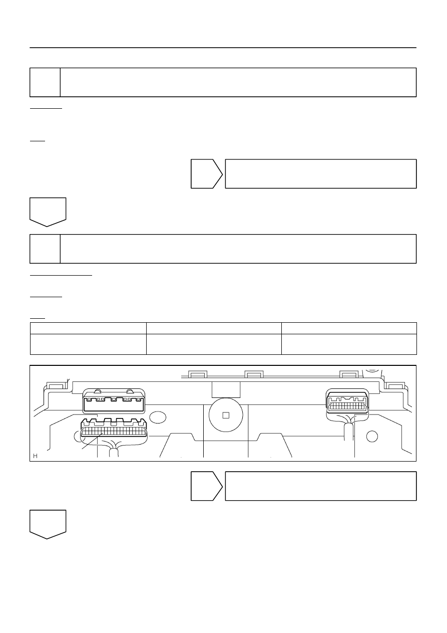
Combination Meter Wire Harness View:
C5–34
C5
–
DIAGNOSTICS
POWER SEAT CONTROL SYSTEM (w/ Driving Position
Memory)
DI–1529
1723
INSPECTION PROCEDURE
1
Check combination meter operation.
CHECK:
Check that the ”P” indicator light in the combination meter comes on when the shift lever is moved to the
P position.
OK:
The ”P” indicator light comes on.
NG
Go to combination meter system (See page
OK
2
Check harness and connector (Combination meter).
PREPARATION:
Disconnect the C5 combination meter connector.
CHECK:
Measure the voltage of each terminal of the wire harness side connectors.
OK:
Tester Connection
Condition
Specified Condition
C5–34 – Body ground
Ignition switch is in ON position and shift lever is
in P position
10 to 14 V
OK
Proceed to next circuit inspection shown in
problem symptom table (See page
NG
I28706
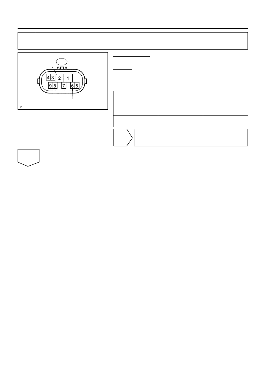
Park/Neutral Position Switch Assy:
P1
RB
PL
DI–1530
–
DIAGNOSTICS
POWER SEAT CONTROL SYSTEM (w/ Driving Position
Memory)
1724
3
Inspect park/neutral position switch assy.
PREPARATION:
Disconnect the P1 switch connector.
CHECK:
Measure the resistance of each terminal of the wire harness
side connectors.
OK:
Tester Connection
(Symbols)
Condition
Specified Condition
P1–2 (RB) – P1–6 (PL)
Shift lever is moved to
P position
Below 1
Ω
P1–2 (RB) – P1–6 (PL)
Shift lever is moved to any
position except P
10 k
Ω
or higher
NG
Replace park/neutral position switch.
OK
Нет комментариевНе стесняйтесь поделиться с нами вашим ценным мнением.
Текст