Toyota Sequoia (2005). Manual — part 671
A08932
Lift
A04857
EM–94
–
ENGINE MECHANICAL
ENGINE UNIT (4WD)
2673
(c)
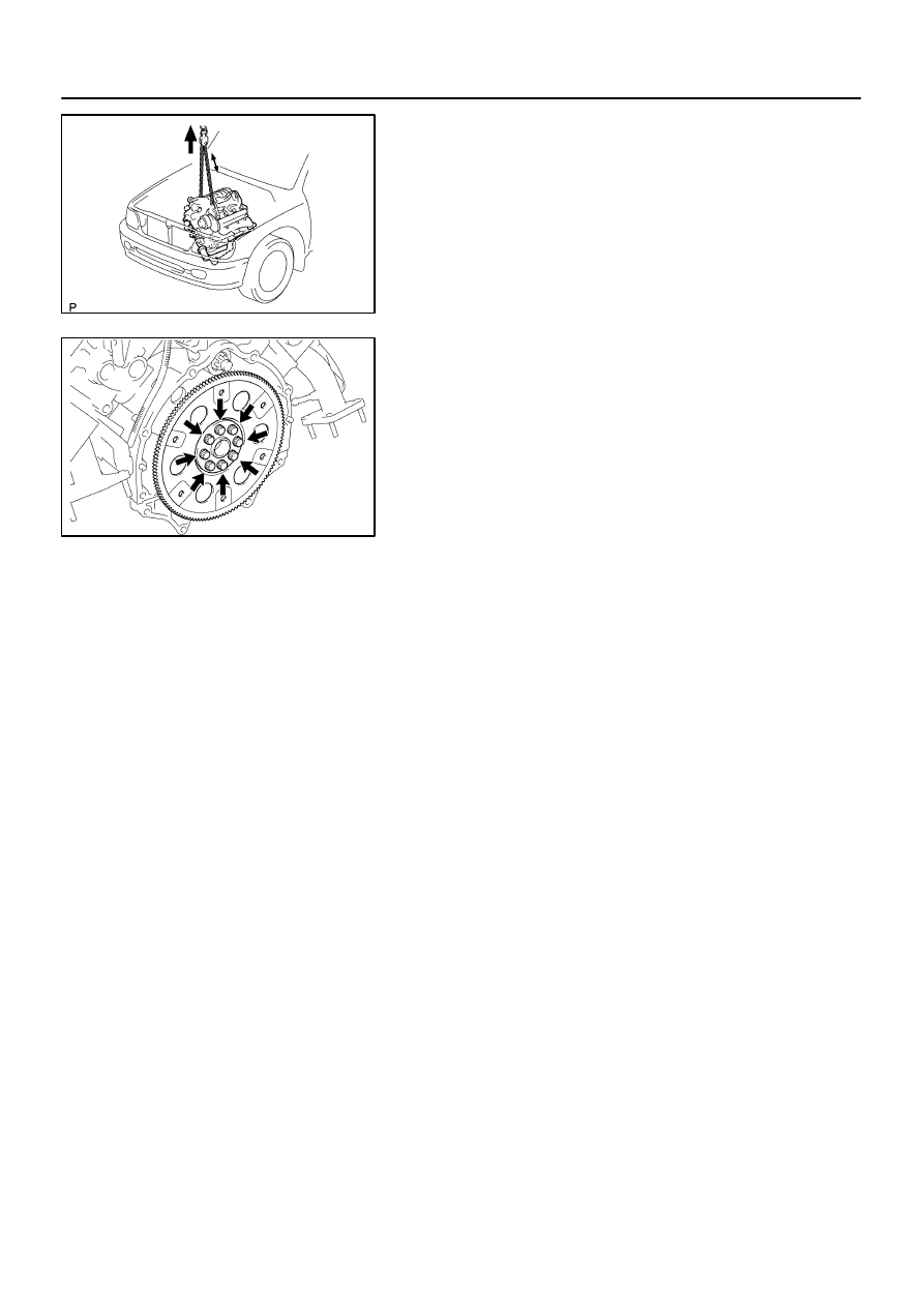
Lift the engine out of the vehicle slowly and carefully.
HINT:
Make sure the engine is clear of all wiring, hoses and cables.
(d)
Place the engine and transmission assembly onto the
stand.
19.
REMOVE DRIVE PLATE
Remove the 8 bolts, front spacer, drive plate and rear spacer.
EM11Y–07
A04869
Adhesive
A04857
1
2
3
4
7
6
8
5
A05137
Painted
Mark
90
°
90
°
A08933
Lower
–
ENGINE MECHANICAL
ENGINE UNIT (4WD)
EM–95
2674
INSTALLATION
1.
INSTALL DRIVE PLATE
HINT:
The mounting bolts are tightened in 2 progressive steps
(steps (c) and (e)).
If any one of the mounting bolts is broken or deformed, re-
place it.
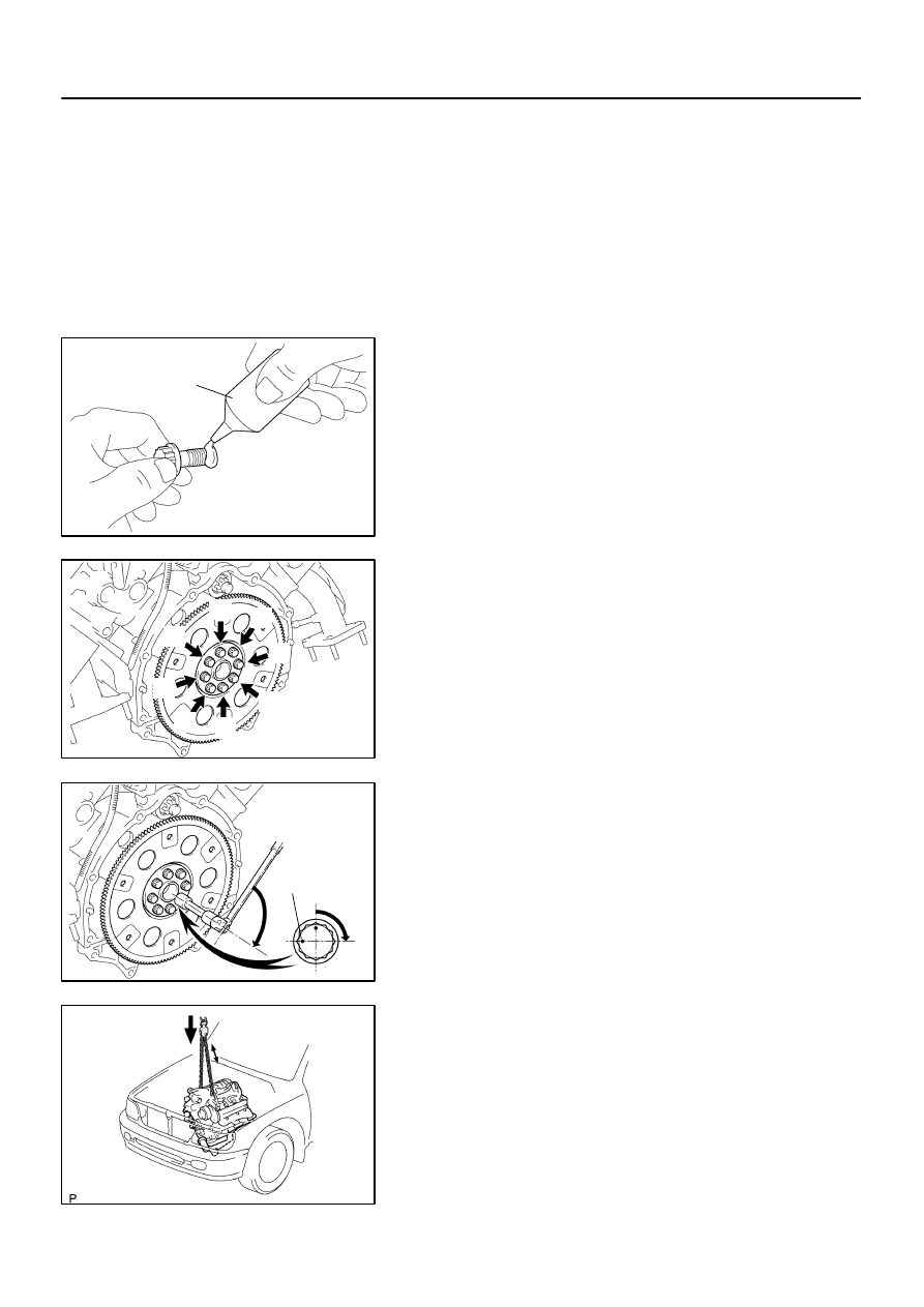
(a)
Apply adhesive to 2 or 3 threads of the mounting bolt end.
Adhesive:
Part No. 08833–00070, THREE BOND 1324 or equiva-
lent
(b)
Install the front spacer, drive plate and rear spacer on the
crankshaft.
(c)
Install and uniformly tighten the 8 mounting bolts in sever-
al passes, in the sequence shown.
Torque: 49 N·m (500 kgf·cm, 36 ft·lbf)
If any one of the mounting bolts does not meet the torque speci-
fication, replace the mounting bolt.
(d)
Mark the mounting bolt with paint.
(e)
Retighten the mounting bolts by 90
°
in the numerical or-
der shown.
(f)
Check that the painted mark is now at a 90
°
angle to (e).
2.
INSTALL ENGINE ASSEMBLY IN VEHICLE
(a)
Attach the engine chain hoist to the engine hangers.
(b)
Slowly lower the engine assembly into the engine
compartment.
(c)
Attach the engine mounting brackets to the frame brack-
ets.
A08936
A08907
A08905
EM–96
–
ENGINE MECHANICAL
ENGINE UNIT (4WD)
2675
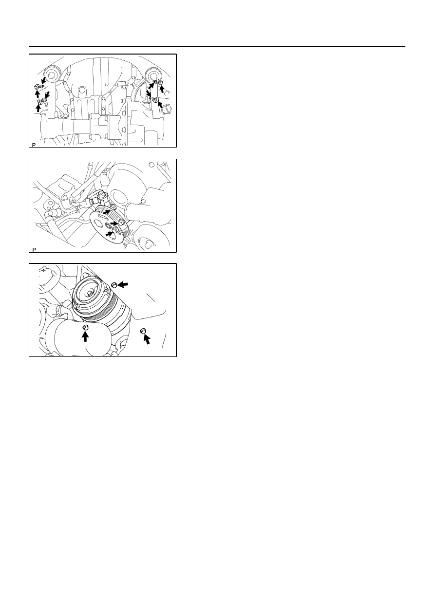
(d)
Install the engine mounting brackets to the frame brack-
ets with the 2 nuts and 4 bolts.
Torque: 38 N·m (388 kgf·cm, 28 ft·lbf)
(e)
Remove the engine chain hoist.
3.
INSTALL PS PUMP
Install the PS pump with the 3 bolts.
Torque: 17 N·m (175 kgf·cm, 13 ft·lbf)
4.
INSTALL A/C COMPRESSOR
(a)
Install the A/C compressor with the 3 bolts.
Torque: 49 N·m (500 kgf·cm, 36 ft·lbf)
(b)
Connect the A/C compressor connector.
5.
CONNECT HOSES, WIRES, CONNECTORS, CLAMPS,
GROMMET AND CABLES
(a)
Connect the 2 PS air hoses to hose clamp on the No.3 RH
timing belt cover.
(b)
Connect the generator wire.
(c)
Connect the generator connector.
(d)
Connect the hose clamp for the PS air hose.
(e)
Connect the PS air hose to the upper intake manifold.
(f)
Connect the 2 heater hoses.
(g)
Connect the ground strap to the cowl panel.
(h)
Connect the fuel inlet hose and clamps.
(i)
Connect the fuel return hose and clamp.
(j)
Connect the air inlet hose to the charcoal canister.
(k)
Connect the EVAP hose to the charcoal canister.
(l)
Connect the brake booster tube.
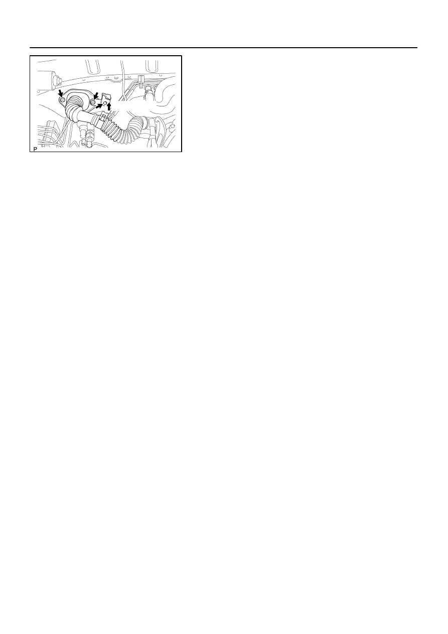
6.
CONNECT ENGINE WIRE TO CABIN
(a)
Push into the engine wire through the cowl panel.
A09152
Connect
–
ENGINE MECHANICAL
ENGINE UNIT (4WD)
EM–97
2676
(b)
Install the engine wire bracket with the 2 nuts and bolt and
connect the engine wire to the bracket.
(c)
Connect the 3 connectors to the ECM.
(d)
Connect the 2 wire harness connectors (cassette con-
nector).
(e)
Install the ECM with the 3 screws.
(f)
Install the lower No.2 panel.
(g)
Install the glove compartment door.
7.
INSTALL FAN PULLEY, FAN, FLUID COUPLING AND
DRIVE BELT
(a)
Temporarily install the fan pulley, the fan and fluid cou-
pling assembly with the 4 nuts.
(b)
Install the drive belt. (See page
(c)
Tighten the 4 nuts holding the fluid coupling to the fan
bracket.
8.
INSTALL AIR CLEANER AND INTAKE AIR CONNEC-
TOR PIPE ASSEMBLY
(a)
Install the air cleaner case with the 3 bolts.
Torque: 5.0 N·m (51 kgf·cm, 44 in.·lbf)
(b)
Connect the intake air connector to the throttle body.
(c)
Connect the MAF meter connector.
(d)
Install the suction hose to the intake air connector.
(e)
Connect the PS air hose, air inlet hose for EVAP, PCV
hose and MAF meter connector to the intake air connec-
tor.
9.
INSTALL THROTTLE BODY COVER
10.
INSTALL TRANSMISSION (See page
)
11.
INSTALL RADIATOR ASSEMBLY (See page
12.
INSTALL FRONT STABILIZER BAR
(See page
13.
INSTALL FRONT AND REAR PROPELLER SHAFTS
(See page
14.
INSTALL FRONT EXHAUST PIPES
(See page
)
15.
INSTALL BATTERY CABLES
(a)
Connect the battery positive (+) terminal cable.
(b)
Connect the battery negative (–) cable to the battery and
left fender apron.
(c)
Connect the clamp on battery negative (–) cable to No.2
relay box.
16.
PERFORM INITIALIZATION
Some system need initialzation when disconnecting the cable
from the battery terminal.
17.
FILL WITH ENGINE COOLANT (See page
18.
FILL WITH ENGINE OIL (See page
19.
START ENGINE AND CHECK FOR LEAKS
20.
INSTALL ENGINE UNDER COVERS
21.
INSTALL HOOD
Нет комментариевНе стесняйтесь поделиться с нами вашим ценным мнением.
Текст