Toyota Sequoia (2005). Manual — part 672
EM–98
–
ENGINE MECHANICAL
ENGINE UNIT (4WD)
2677
22.
PERFORM ROAD TEST
Check for abnormal noise, shock, slippage, correct shift points
and smooth operation.
23.
RECHECK ENGINE COOLANT AND OIL LEVELS
EM0E9–17
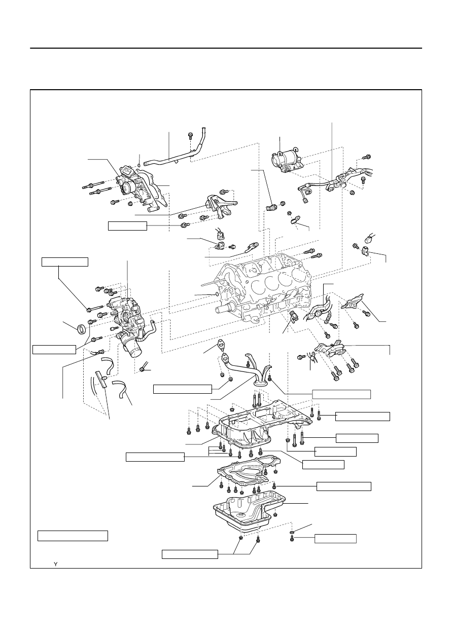
A23375
Engine Mounting Bracket
Oil Pump
Crankshaft
Front Oil
Seal
Crankshaft Position
Sensor Connector
No.1 Oil Pan
Non–reusable part
Precoated part
Oil Strainer
Engine
Mounting
Bracket
VVT Sensor 2
Connector
Knock Sensor 1
Knock Sensor 2
Engine Coolant
Drain Union
Starter
No.2 Oil Pan
Oil Pan Baffle Plate
x 8
Water Pump
Gasket
O–Ring
Engine
Wire
Engine
Wire
Cover
VVT
Sensor 1
Engine Coolant
Drain Union
36 (370, 27)
30.5 (310, 22)
x 5
Oil Pressure
Sender Gauge
Connector
7.5 (76, 66 in.·lbf)
7.5 (76, 66 in.·lbf)
7.5 (76, 66 in.·lbf)
N·m (kgf·cm, ft·lbf) : Specified torque
x 20
Clamp
Engine Wire Protector
Tape
28 (290, 21)
7.5 (76, 66 in.·lbf)
28 (290, 21)
Water Bypass Pipe
7.5 (76, 66 in.·lbf)
O–Ring
Gasket
Engine
Wire
15.5 (160, 11)
39 (400, 29)
Gasket
28 (290, 21)
7.5 (76, 66 in.·lbf)
x 4
–
ENGINE MECHANICAL
CYLINDER BLOCK
EM–99
2678
CYLINDER BLOCK
COMPONENTS
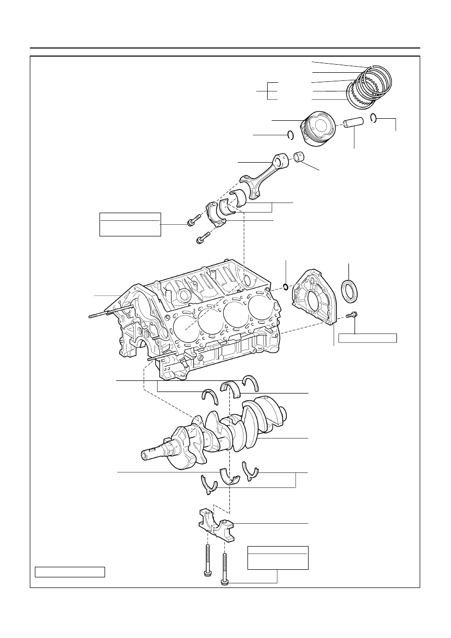
A04847
No.1 Piston Ring
No.2 Piston Ring
Oil Ring
Side Rail
Expander
Side Rail
Connecting Rod
Connecting Rod Bearing
Connecting Rod Cap
Cylinder Block
Snap Ring
Piston Pin
Crankshaft
Rear Oil Seal
O–Ring
Rear Oil Seal Retainer
Upper Main Bearing
Snap Ring
Piston
Upper Crankshaft
Thrust Washer
Lower Main Bearing
Lower Crankshaft
Thrust Washer
Main Bearing Cap
Non–reusable part
x 7
Crankshaft
N·m (kgf·cm, ft·lbf) : Specified torque
Connecting Rod Bushing
See page
1st 24.5 (250, 18)
2nd Turn 90
°
1st 27 (275, 20)
2nd Turn 90
°
8.0 (80, 71 in.·lbf)
EM–100
–
ENGINE MECHANICAL
CYLINDER BLOCK
2679
EM122–05
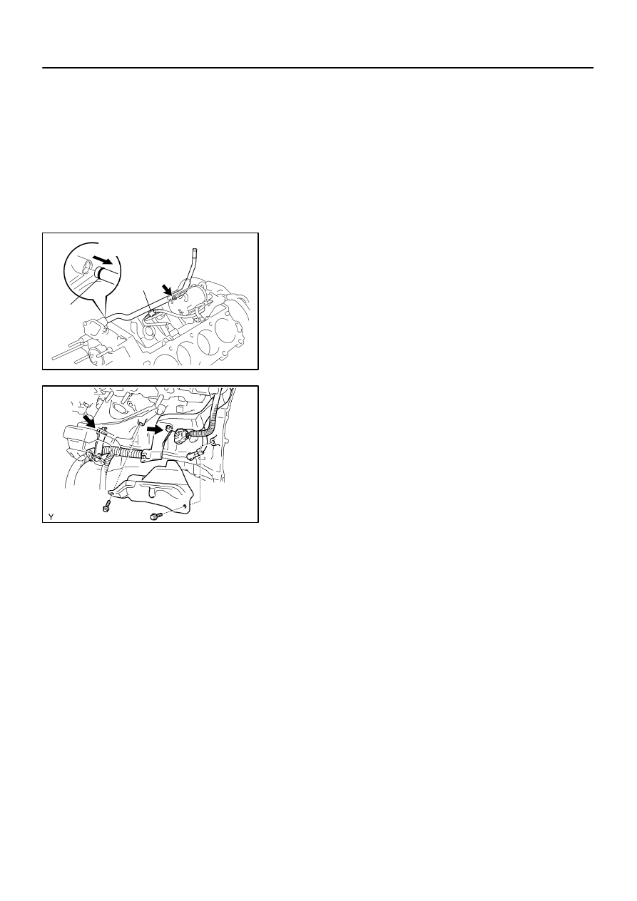
A05112
Pull
Wire
Clamp
O–Ring
A08472
LH Side
–
ENGINE MECHANICAL
CYLINDER BLOCK
EM–101
2680
DISASSEMBLY
1.
INSTALL ENGINE TO ENGINE STAND
2.
REMOVE TIMING BELT AND PULLEYS
(See page
3.
REMOVE CYLINDER HEAD (See page
4.
REMOVE WATER BYPASS PIPE
(a)
Disconnect the wire clamp (for knock sensor 1, 2) from
bracket of the water bypass pipe.
(b)
Remove the bolt.
(c)
Pull out the water bypass pipe from the water pump.
(d)
Remove the O–ring from the water bypass pipe.
5.
REMOVE STARTER (See page
6.
REMOVE KNOCK SENSORS (See page
7.
REMOVE VVT SENSORS (See page
8.
DISCONNECT ENGINE WIRE FROM LH SIDE OF CYL-
INDER BLOCK
(a)
Remove the 2 bolts and engine wire cover from the LH
side of the cylinder block.
(b)
Remove the 2 bolts, disconnect the brackets on the en-
gine wire from the cylinder block and engine mounting
bracket.
9.
REMOVE OIL COOLER PIPE BRACKET FOR A/T
Remove the bolt and bracket.
10.
REMOVE ENGINE MOUNTING BRACKETS
Remove the 4 bolts and mounting bracket. Remove the 2
mounting brackets.
11.
REMOVE WATER PUMP (See page
12.
REMOVE NO.2 OIL PAN (See page
13.
REMOVE OIL PAN BAFFLE PLATE
14.
REMOVE NO.1 OIL PAN (See page
15.
REMOVE OIL STRAINER
16.
17.
REMOVE ENGINE COOLANT DRAIN UNIONS
Remove the 2 drain unions.
Нет комментариевНе стесняйтесь поделиться с нами вашим ценным мнением.
Текст