Toyota Sequoia (2005). Manual — part 69

–
DIAGNOSTICS
ENGINE
DI–79
273
DTC
P0011
Camshaft Position ”A” –Timing Over–
Actuator or System Performance (Bank 1)
DTC
P0012
Camshaft Position ”A” –Timing Over–
Retarded (Bank 1)
DTC
P0021
Camshaft Position ”A” –Timing Over–
Actuator or System Performance (Bank 2)
DTC
P0022
Camshaft Position ”A” –Timing Over–
Retarded (Bank 2)
CIRCUIT DESCRIPTION
Refer to DTCs P0010 on page
DTC No.
DTC Detecting Condition
Trouble Area
P0011
P0021
Advanced cam timing:
After engine is warmed up and engine speed is at 400 to
4,000 rpm, condition (a) continues. (1 trip detection logic)
(a) Valve timing does not change from current valve timing
Valve timing
OCV
P0012
P0022
Retarded cam timing:
After engine is warmed up and engine speed is at 400 to
4,000 rpm, condition (a) continues. (2 trip detection logic)
(a) Valve timing does not change from current valve timing
OCV
VVT controller assembly
ECM
MONITOR DESCRIPTION
The ECM optimizes the valve timing using the VVT (Variable Valve Timing) system to control the intake valve
camshaft. The VVT system includes the ECM, the OCV (Oil Control Valve) and the VVT controller. The ECM
sends a target ”duty–cycle” control signal to the OCV. This control signal, applied to the OCV, regulates the
oil pressure supplied to the VVT controller. The VVT controller can advance or retard the intake valve cam-
shaft.
Example:
A DTC will set if: 1) the difference between the target and actual valve timing is more than 5 degrees of the
crankshaft angle (CA) and the condition continues for more than 4.5 sec.; or 2) the OCV is forcibly activated
63 times or more.
Advanced cam DTCs are subject to ”1 trip” detection logic.
Retarded cam DTCs are subject to ”2 trip” detection logic.
DIAON–02

DI–80
–
DIAGNOSTICS
ENGINE
274
MONITOR STRATEGY
P0011
VVT system advance (Bank 1)
R l t d DTC
P0012
VVT system retard (Bank 1)
Related DTCs
P0021
VVT system advance (Bank 2)
P0022
VVT system retard (Bank 2)
Main sensors/components
Camshaft position sensor
Required sensors/components
Related sensors/components
Engine coolant temperature sensor,
Crankshaft position sensor
Frequency of operation
Once per drive cycle
Duration
10 sec.
MIL operation
P0011, P0021: Immediate
P0012, P0022: 2 driving cycles
Sequence of operation
None
TYPICAL ENABLING CONDITIONS
It
Specification
Item
Minimum
Maximum
The monitor will run whenever these
DTCs are not present
See page
Battery voltage
11 V
–
Throttle position learning
Completed
Engine RPM
400 rpm
4,000 rpm
Engine coolant temperature
75
C (167
F)
100
C (212
F)
TYPICAL MALFUNCTION THRESHOLDS
Detection Criteria
Threshold
Deviation of valve timing
More than 5
CA
OCV activation
63 times or more
Response of valve timing
1 sec./1
CA or more
WIRING DIAGRAM
Refer to DTCs P0010 on page
INSPECTION PROCEDURE
HINT:
Bank 1 refers to bank that includes cylinder No. 1.
Bank 2 refers to bank that does not include cylinder No. 1.
If DTC P0011, P0012 is displayed, check the bank 1 VVT system.
If DTC P0021, P0022 is displayed, check the bank 2 VVT system.
Read freeze frame data using the hand–held tester. Freeze frame data records the engine conditions
when a malfunction is detected. When troubleshooting, it is useful for determining whether the vehicle
was running or stopped, the engine was warmed up or not, the air–fuel ratio was lean or rich, etc. at
the time of the malfunction.

–
DIAGNOSTICS
ENGINE
DI–81
275
1
Check operation of OCV.
PREPARATION:
(a)
Connect the hand–held tester to the DLC3.
(b)
Start the engine and warm it up.
(c)
Turn the ignition switch to ON and turn the hand–held tester ON.
CHECK:
(a)
Select the item: DIAGNOSIS / ENHANCED OBD II / ACTIVE TEST / VVT CTRL B1 or VVT CTRL B2.
(b)
Using the hand–held tester, operate the OCV and check the engine speed.
OK:
Standard:
Tester Operation
Specified Condition
OCV is OFF
Normal engine speed
OCV is ON
Rough idle or engine stall
OK
VVT system is OK.*
*: DTC P0011, P0012, P0021 or P0022 is also output when a
foreign object is detected in some parts of the system in the en-
gine oil, and then the system returns to normal in a short time.
As ECM is controlled to eject a foreign object, there is no prob-
lem on the VVT. There is also no problem on the VVT as the oil
filter should catch the foreign object in the engine oil.
NG
2
Check valve timing (See page
).
NG
Adjust valve timing.
OK
A02397
OCV Signal Waveform
200 msec./Division
5 V/
Division
GND
(A)
(A)
(A)
B17414
ECM Connector
E6
OC1+
OC1–
OC2+
OC2–
E1
B12806
Ohmmeter
DI–82
–
DIAGNOSTICS
ENGINE
276
3
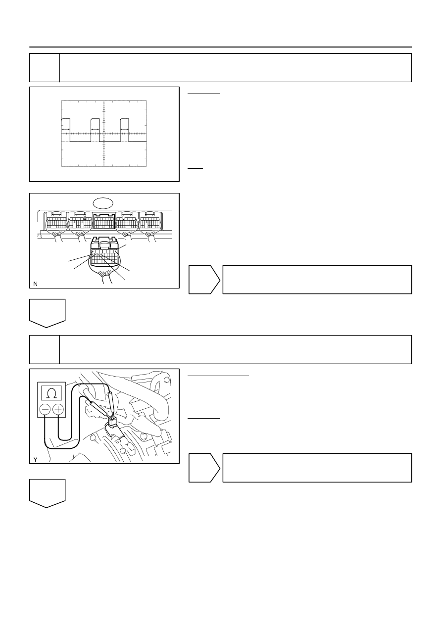
Check voltage between terminals OCV+ and OCV– of ECM connector.
CHECK:
(a)
Inspection using the oscilloscope.
(b)
During idling, check the waveform between the specified
terminals of the E6 ECM connector.
HINT:
The waveform frequency (A) is lengthened as the engine speed
becomes higher.
OK:
Standard:
The correct waveform is as shown.
NG
Check and replace ECM (See page
).
OK
4
Check OCV.
PREPARATION:
(a)
Remove the V–bank cover.
(b)
Remove the air cleaner inlet and intake air connector.
(c)
Disconnect the oil control valve connector.
CHECK:
(a)
Using an Ohmmeter, measure the resistance between
the terminals.
Resistance: 6.9 – 7.9
Ω
at 20
°
C (68
°
F)
NG
Replace OCV, and then go to step 6.
OK
Нет комментариевНе стесняйтесь поделиться с нами вашим ценным мнением.
Текст