Toyota Sequoia (2005). Manual — part 67

–
DIAGNOSTICS
ENGINE
DI–71
265
P2401
(
Evaporative Emission System
Leak Detection Pump Control
Circuit Low
Pump module
Connector/Wire harness (between pump module and ECM)
ECM
P2402
(
Evaporative Emission System
Leak Detection Pump Control
Circuit High
Pump module
Connector/Wire harness (between pump module and ECM)
ECM
P2419
(
Evaporate Emission System
Switching Valve Control Circuit
Low
Pump module
Connector/Wire harness (between pump module and ECM)
ECM
P2420
(
Evaporate Emission System
Switching Valve Control Circuit
High
Pump module
Connector/Wire harness (between pump module and ECM)
ECM
P2430
(
Secondary Air Injection System
Air Flow/Pressure Sensor Circuit
Bank 1
Pressure sensor
Open or short in pressure sensor circuit
Vacuum hose
Check valve
ECM
P2431
(
Secondary Air Injection System
Air Flow/Pressure Sensor Circuit
Range/Performance Bank 1
Pressure sensor
Open or short in pressure sensor circuit
Vacuum hose
Check valve
ECM
P2432
(
Secondary Air Injection System
Air Flow/Pressure Sensor Circuit
Low Bank 1
Pressure sensor
Open or short in pressure sensor circuit
Vacuum hose
Check valve
ECM
P2433
(
Secondary Air Injection System
Air Flow/Pressure Sensor Circuit
High Bank 1
Pressure sensor
Open or short in pressure sensor circuit
Vacuum hose
Check valve
ECM
P2440
(
Secondary Air Injection System
Switching Valve Stuck Open
Bank 1
Electromagnetic air switching valve
Air switching valve No.2 (Bank 1 and/or 2)
VSV for air injection system (Bank 1 and/or 2)
Air injection driver
Air injection driver circuit
ECM
P2441
(
Secondary Air Injection System
Switching Valve Stuck Close
Bank 1
Vacuum hoses (Throttle body – VSVs for air injection control)
Electromagnetic air switching valve
Air injector pipe (Air switching valve No.2 – exhaust manifold)
Air injection hose
Air switching valve No.2 (Bank 1 and/or 2)
VSV for air injection control (Bank 1 and/or 2)
Air injection driver
Air injection driver circuit
ECM
P2444
(
Secondary Air Injection System
Pump Stuck On Bank 1
Short in air pump circuit
Pressure sensor
Air pump assembly
Open or short in pressure sensor circuit
ECM

DI–72
–
DIAGNOSTICS
ENGINE
266
P2445
(
Secondary Air Injection System
Pump Stuck On Bank 1
Air pump fuse
Vacuum hose
Air pump assembly
Open in air pump circuit
Air injection system piping
Pressure sensor
Open or short in pressure sensor circuit
ECM
P2610
(
ECM/PCM Internal Engine Off
Timer Performance
ECM
P2714
(
Pressure Control Solenoid ”D”
Performance (Shift Solenoid
Valve SLT)
Electronic control automatic transmission (ECT)
P2716
(
Pressure Control Solenoid ”D”
Electrical (Shift Solenoid Valve
SLT)
Electronic control automatic transmission (ECT)
P2740
(
Transmission Fluid Temperature
Sensor ”B” Circuit
Electronic control automatic transmission (ECT)
P2742
(
Transmission Fluid Temperature
Sensor ”B” Circuit Low Input
Electronic control automatic transmission (ECT)
2743
(
Transmission Fluid Temperature
Sensor ”B” Circuit High Input
Electronic control automatic transmission (ECT)
P2757
(
Torque Converter clutch Pres-
sure Control Solenoid Perfor-
mance (Shift Solenoid Valve
SLU)
Electronic control automatic transmission (ECT)
P2759
(
Torque Converter clutch Pres-
sure Control Solenoid Electrical
(Shift Solenoid Valve SLU)
Electronic control automatic transmission (ECT)
P2772
(
Transfer L4 SW Circuit
Electronic control automatic transmission (ECT)
P2A00
(
A/F Sensor Circuit Slow Re-
sponse (Bank 1 Sensor 1)
Open or short in A/F sensor (sensor 1) circuit
A/F sensor (sensor 1)
ECM
P2A03
(
A/F Sensor Circuit Slow Re-
sponse (Bank 2 Sensor 1)
Open or short in A/F sensor (sensor 1) circuit
A/F sensor (sensor 1)
ECM
B2799
)
Engine Immobilizer System Mal-
function
Immobilizer system
–
U0001
(
High Speed CAN Communica-
tion Bus
ECM
*1
: – . MIL does not light up.
. MIL lights up.
*2
: MIL lights up or blinks.
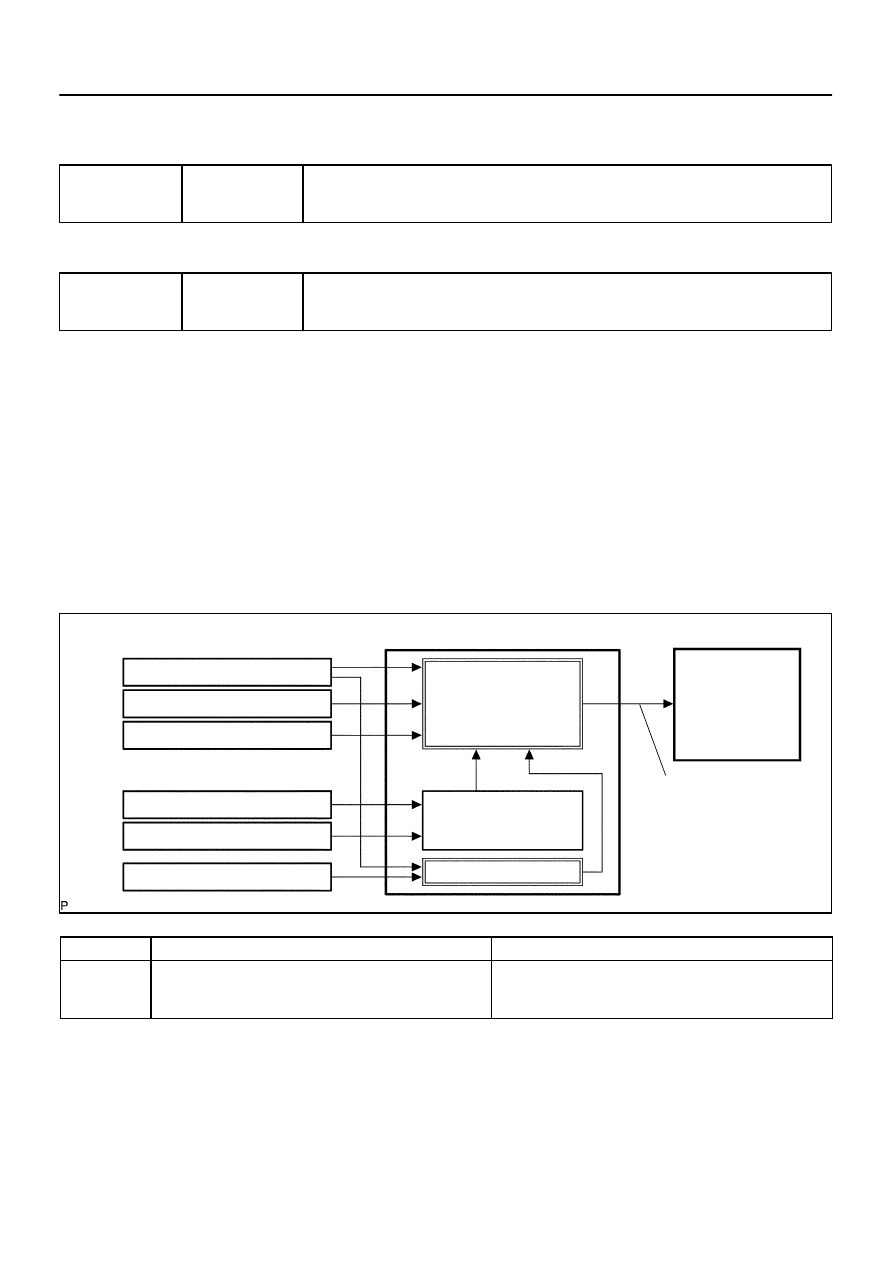
DID82–01
A20891
Mass Air Flow Sensor
Crankshaft Position Sensor
Actual Valve Timing
Correction
Target Valve Timing
Feedback
Duty Control
ECM
Camshaft Timing
Oil Control
Valve (OCV)
Vehicle Speed Signal
Engine Coolant Temp. Sensor
Throttle Position Sensor
Camshaft Position Sensor
–
DIAGNOSTICS
ENGINE
DI–73
267
CIRCUIT INSPECTION
DTC
P0010
Camshaft Position ”A” Actuator circuit
(Bank 1)
DTC
P0020
Camshaft Position ”A” Actuator circuit
(Bank 2)
CIRCUIT DESCRIPTION
The Variable Valve Timing (VVT) system includes the ECM, the Oil Control Valve (OCV) and the VVT control-
ler. The ECM sends a target ”duty–cycle” control signal to the OCV. This control signal, applied to the OCV,
regulates the oil pressure supplied to the VVT controller. Camshaft timing control is performed based on en-
gine operation conditions such as intake air volume, throttle position and engine coolant temperature.
The ECM controls the OCV, based on the signals output from the sensors. The VVT controller regulates the
intake camshaft angle using oil pressure through the OCV. As a result, the relative position between the cam-
shaft and the crankshaft is optimized, and the engine torque improves, fuel economy improves, and exhaust
emissions decrease under overall driving conditions. Also, the ECM detects the actual valve timing using
signals from the camshaft position sensor and the crankshaft position sensor, and performs feedback con-
trol. This is how target valve timing is verified by the ECM.
DTC No.
DTC Detecting Condition
Trouble Area
P0010
P0020
Open or short in OCV circuit
Open or short in OCV circuit
OCV
ECM

DI–74
–
DIAGNOSTICS
ENGINE
268
MONITOR DESCRIPTION
After the ECM sends the ”target” duty–cycle signal to the OCV (Oil Control Valve), the ECM monitors the
OCV current to establish an ”actual” duty–cycle. When the actual duty–cycle ratio varies from the target
duty–cycle, the ECM sets a DTC.
MONITOR STRATEGY
R l t d DTC
P0010
VVT oil control valve bank 1 range check
Related DTCs
P0020
VVT oil control valve bank 2 range check
Required sensors/components
OCV
Frequency of operation
Continuous
Duration
1 sec.
MIL operation
Immediate
Sequence of operation
None
TYPICAL ENABLING CONDITIONS
It
Specification
Item
Minimum
Maximum
The monitor will run whenever this DTC is
not present
See page
Battery voltage
11 V
13 V
Target duty ratio
–
70%
Starter
OFF
Current cut status
Not cut
TYPICAL MALFUNCTION THRESHOLDS
Detection Criteria
Threshold
Either of the following conditions is met:
Condition 1 or 2
1. Output signal duty for OCV
Output duty ratio is 100% (always ON) but target duty ratio is less than 70%
2. Output signal duty for OCV
Output duty is 3% or less despite the ECM supplying current to the OCV
COMPONENT OPERATING RANGE
Parameter
Standard Value
Output signal duty for OCV
”More than 3%” and ”less than 100%”
Нет комментариевНе стесняйтесь поделиться с нами вашим ценным мнением.
Текст