Toyota Sequoia (2005). Manual — part 796
F07754
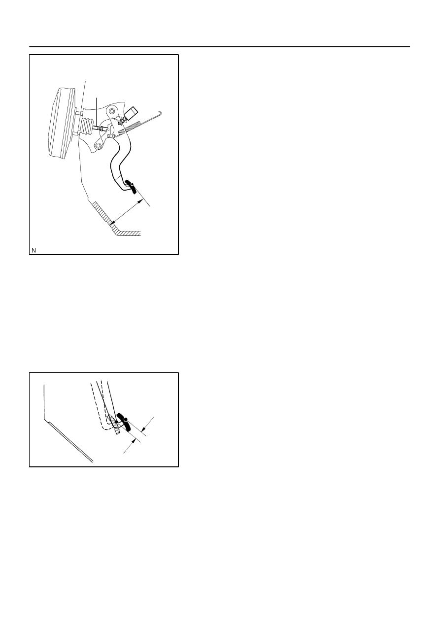
Pedal Height
Push Rod
BR107–04
R00085
Pedal Free Play
BR–6
–
BRAKE
BRAKE PEDAL
3173
BRAKE PEDAL
ON–VEHICLE INSPECTION
1.
CHECK PEDAL HEIGHT
Pedal height from dash panel:
151.1 – 165.1 mm (5.949 – 6.500 in.)
NOTICE:
Do not adjust the pedal height. Doing so by changing the
push rod length of the brake booster will structurally
change the pedal ratio.
If the pedal height is incorrect, check that there is no damage
in brake pedal, brake pedal lever, brake pedal bracket and dash
panel.
Even if there is damage, there is no problem if the
reserve distance is within the standard value.
If necessary, replace them.
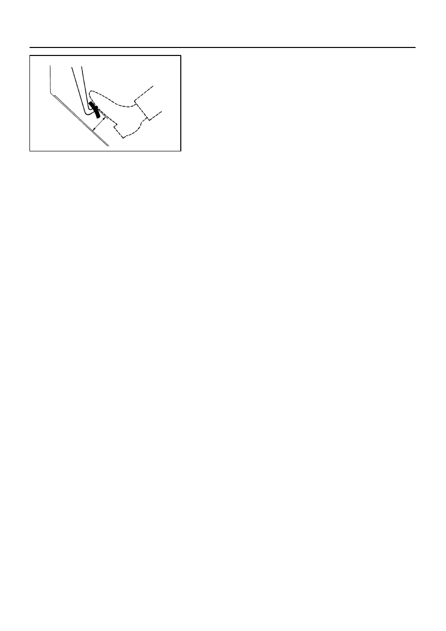
2.
IF NECESSARY, ADJUST STOP LIGHT SWITCH
(a)
Remove the front door scuff plate, cowl side trim, side
panel, lower finish panel and No. 2 heater to register duct
(See page
(b)
Loosen the stop light switch lock nut.
(c)
Push the brake pedal in 5 – 15 mm (0.20 – 0.59 in.), turn
the stop light switch to lock the nut in the position where
the stop light goes off.
(d)
Push the brake pedal in 5 –15 mm (0.20 – 0.59 in.), check
that the stop light lights up.
(e)
Install the No. 2 heater to register duct, lower finish panel,
side panel, cowl side trim and front door scuff plate (See
page
3.
CHECK PEDAL FREE PLAY
(a)
Stop the engine and depress the brake pedal several
times until there is no more vacuum left in the booster.
(b)
Push in the pedal by hand until the second point of resis-
tance begins to be felt, then measure the distance as
shown in the illustration.
Pedal free play: 1 – 6 mm (0.04 – 0.24 in.)
HINT:
The free play to the first point of resistance is due to the play
between the clevis and pin. It is 1 – 3 mm (0.04 – 0.12 in.) at the
pedal.
If incorrect, check the stop light switch clearance. If the clear-
ance is OK, then troubleshoot the brake system.
Stop light switch clearance:
0.5 – 2.4 mm (0.020 – 0.095 in.)
R00135
Pedal Reserve Distance
–
BRAKE
BRAKE PEDAL
BR–7
3174
4.
CHECK PEDAL RESERVE DISTANCE
Release the parking brake.
With the engine running, depress the pedal and measure the
pedal reserve distance, as shown.
Pedal reserve distance from asphalt sheet at 490 N
(50 kgf, 110.2 lbf): More than 95 mm (3.74 in.)
If the reserve distance is incorrect, troubleshoot the brake sys-
tem.
BR108–06
F13309
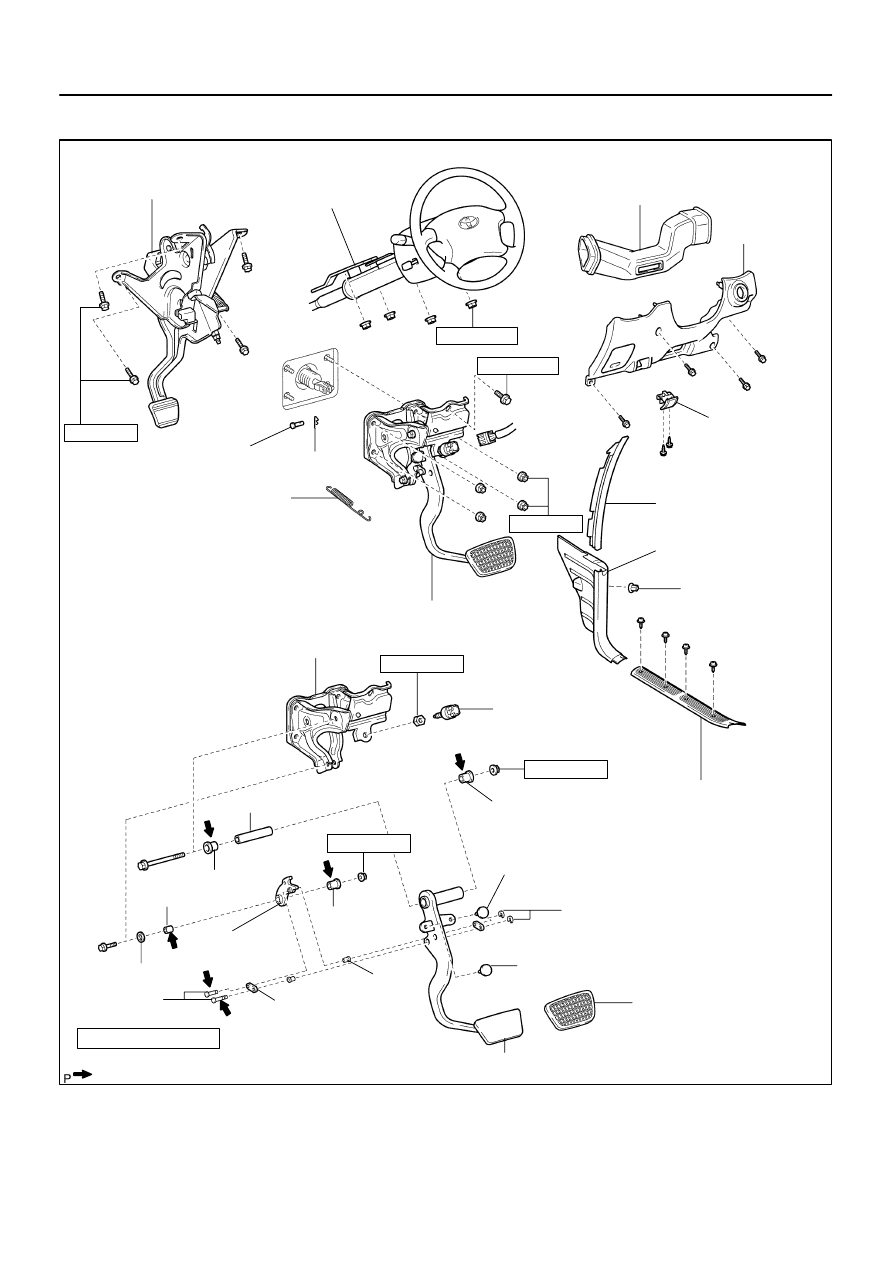
No. 2 Heater to
Register Duct
Lower Finish
Panel
Hood Lock
Release Lever
Clevis Pin
Pedal Bracket
Stop Light Switch
Brake Pedal
Collar
Pedal Return Spring
Pedal Pad
Clip
Pin
E–ring
Brake Pedal
Link
: Specified torque
N·m (kgf·cm, ft·lbf)
Non–reusable part
Lithium soap base glycol grease
Bushing
Cushion
Bushing
13 (130, 9)
19 (195, 14)
Clip
Parking Brake
Pedal Assembly
26 (260, 19)
Cowl Side Trim Board
Front Door Scuff Plate
Brake Pedal Assembly
Lock Nut
Steering Column
Assembly
Cushion
34 (350, 25)
Collar
Brake Pedal
Lever
Cushion
Collar
Bushing
34 (350, 25)
13 (130, 9)
25 (260, 19)
Side Panel
BR–8
–
BRAKE
BRAKE PEDAL
3175
COMPONENTS
F13902
BR109–04
F13896
Adjusting
Nut
Lock Nut
–
BRAKE
PARKING BRAKE PEDAL
BR–9
3176
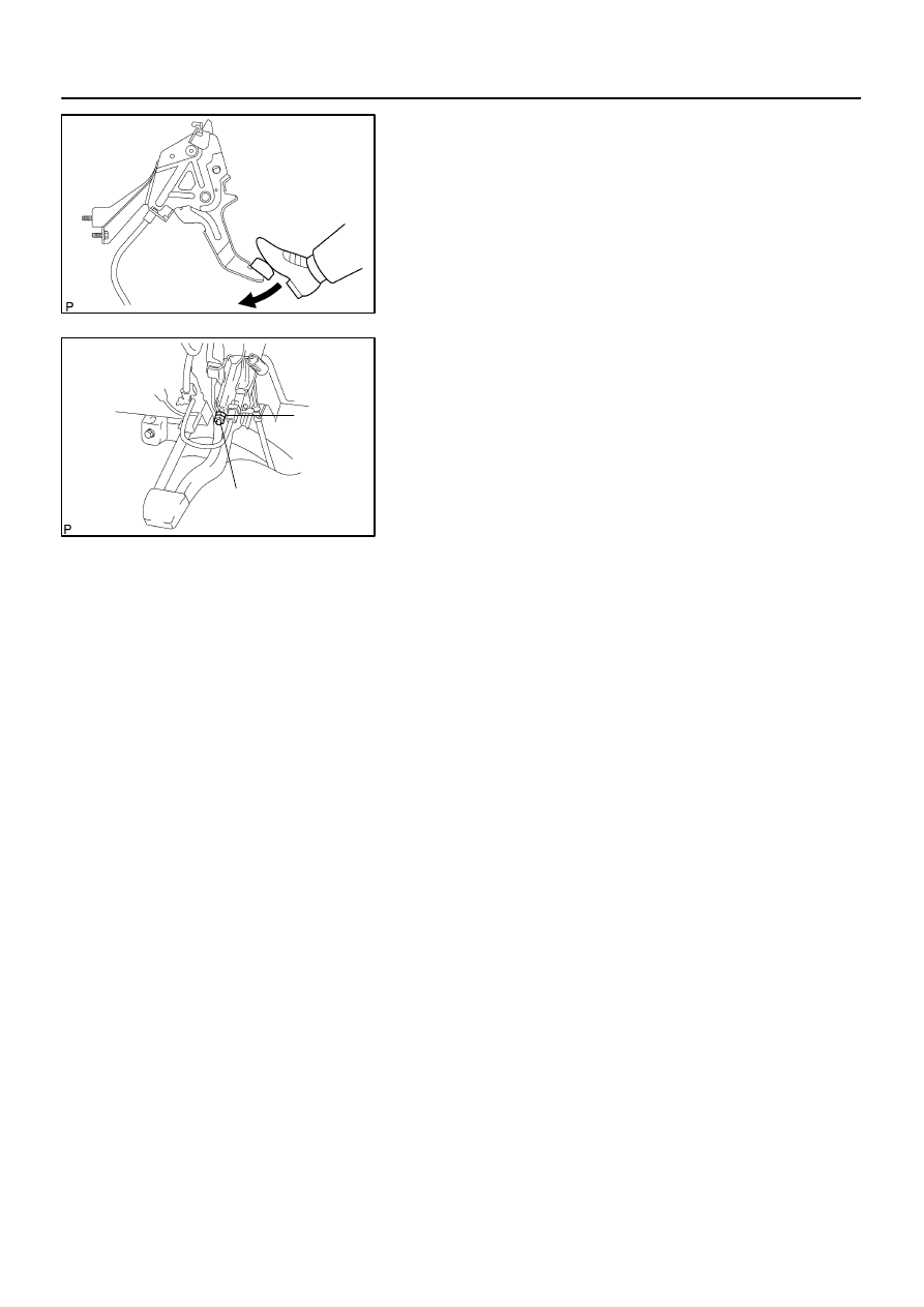
PARKING BRAKE PEDAL
ON–VEHICLE INSPECTION
1.
CHECK PARKING BRAKE PEDAL TRAVEL
Depress the parking brake pedal all the way and count the num-
ber of clicks.
Parking brake pedal travel at 300 N (31 kgf, 67 lbf):
6 – 9 clicks
If incorrect, adjust the parking brake.
2.
IF NECESSARY, ADJUST PARKING BRAKE PEDAL
TRAVEL
HINT:
Before adjusting the parking brake, make sure that the rear
brake shoe clearance has been adjusted. For shoe clearance
adjustment, see step 1 on page
.
(a)
Remove the front door scuff plate, cowl side trim board,
side panel, lower finish panel and No. 2 heater to register
duct (See page
(b)
Loosen the lock nut and turn the adjusting nut until the
pedal travel is correct.
(c)
Tighten the lock nut.
Torque: 5.4 N·m (55 kgf·cm, 48 in.·lbf)
(d)
Install the No. 2 heater to register duct, lower finish panel,
side panel, cowl side trim and front door scuff plate.
Нет комментариевНе стесняйтесь поделиться с нами вашим ценным мнением.
Текст