Toyota Sequoia (2005). Manual — part 569
I28600
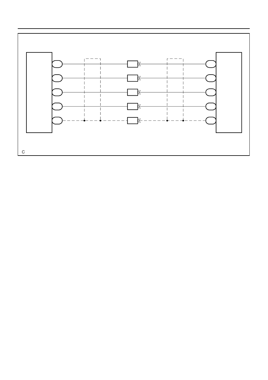
w/o Navigation System:
Radio Receiver Assy
Rear Seat Audio Controller
R–R+
ID2
15
R24
9
W
W
R19
R–R–
16
R24
8
W
G
R19
R–L+
17
R24
7
W
B
R19
R–L–
18
R24
W
R
R19
SG1
14
R24
10
R19
6
9
8
7
10
6
RSR+
RSR–
RSL+
RSL–
SLD1
(Shielded)
(Shielded)
ID2
ID2
ID2
ID2
–
DIAGNOSTICS
REAR SEAT AUDIO SYSTEM
DI–2071
2265
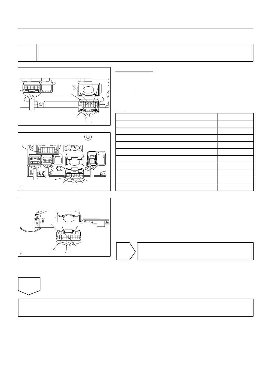
I28606
Radio Receiver Assy
Wire Harness View:
R19
RSR+
RSR–
RSL+
SLD1
RSL–
I28750
Radio and Navigation Assy
Wire Harness View:
R27
R–L+
R–L–
R–R–
R–R+
RSLD
I28337
R–R+
Rear Seat Audio Controller
Wire Harness View:
R–R–
R–L+
SG1
R–L–
R24
DI–2072
–
DIAGNOSTICS
REAR SEAT AUDIO SYSTEM
2266
INSPECTION PROCEDURE
1
Check harness and connector (Radio receiver assy / radio and navigation assy –
Rear seat audio controller).
PREPARATION:
Disconnect the radio receiver assy or radio and navigation con-
nector and rear seat audio controller connector.
CHECK:
Measure the resistance according to the values in the table be-
low.
OK:
Symbol (Tester connection)
Specified condition
R–R+ (R24–9) – R–R+ (R27–15) (*1), RSR+ (R19–15) (*2)
Below 1
Ω
R–R– (R24–8) – R–R– (R27–16) (*1), RSR– (R19–16) (*2)
Below 1
Ω
R–L+ (R24–7) – R–L+ (R27–17) (*1), RSL+ (R19–17) (*2)
Below 1
Ω
R–L– (R24–6) – R–L– (R27–18) (*1), RSL– (R19–18) (*2)
Below 1
Ω
SG1 (R24–10) – RSLD (R27–14), SLD1 (R19–14)
Below 1
Ω
R–R+ (R24–9) – Body ground
10 k
Ω
or higher
R–R– (R24–8) – Body ground
10 k
Ω
or higher
R–L+ (R24–7) – Body ground
10 k
Ω
or higher
R–L– (R24–6) – Body ground
10 k
Ω
or higher
SG1 (R24–10) – Body ground
10 k
Ω
or higher
*1: w/ Navigation System
*2: w/o Navigation System
NG
Repair or replace harness or connector.
OK
Proceed to next circuit inspection shown in problem symptoms table (See page
I28601
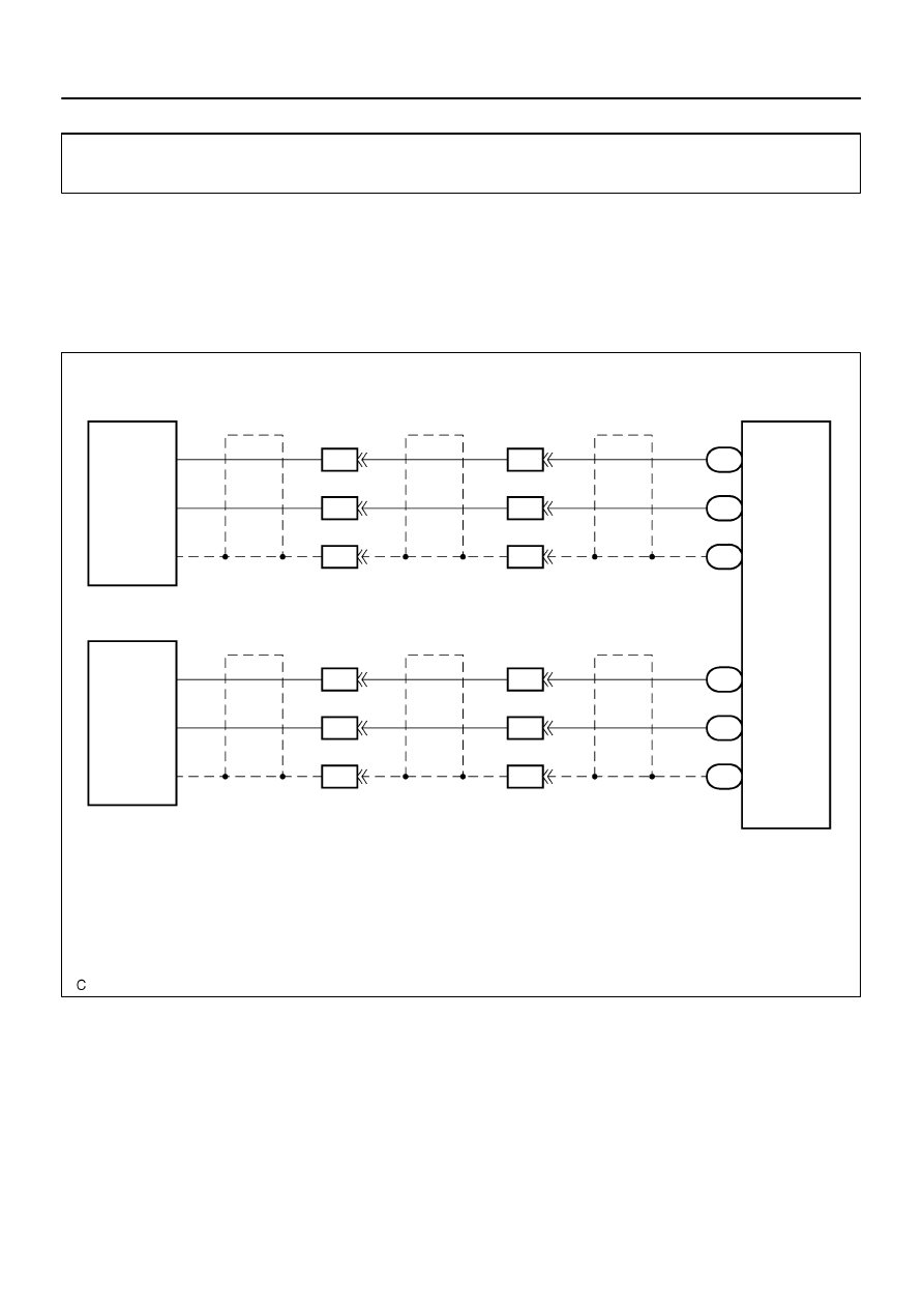
H10
Headphone Terminal LH
Rear Seat Audio Controller
HP1R
ID2
R24
3
BR
W
HP1L
ID2
R24
2
BR
B
SGN1
ID2
R24
1
3
2
1
(Shielded)
(Shielded)
BR
BR
HPR
HPL
SGND
(Shielded)
IF3
8
7
6
H11
Headphone Terminal RH
HP2R
ID2
R24
15
BR
W
HP2L
ID2
R24
14
BR
B
SGN2
ID2
R24
13
19
18
17
(Shielded)
(Shielded)
BR
BR
HPR
HPL
SGND
(Shielded)
20
19
18
1
2
3
1
2
3
IF3
IF3
IF3
IF3
IF3
–
DIAGNOSTICS
REAR SEAT AUDIO SYSTEM
DI–2073
2267
Sound signal circuit (Rear seat audio controller – headphone ter-
minal)
CIRCUIT DESCRIPTION
Music sound which is heard via the headphone terminal of the rear seat audio system is directly sent to the
headphones without being sent through the stereo component amplifier.
WIRING DIAGRAM
DIDAQ–01
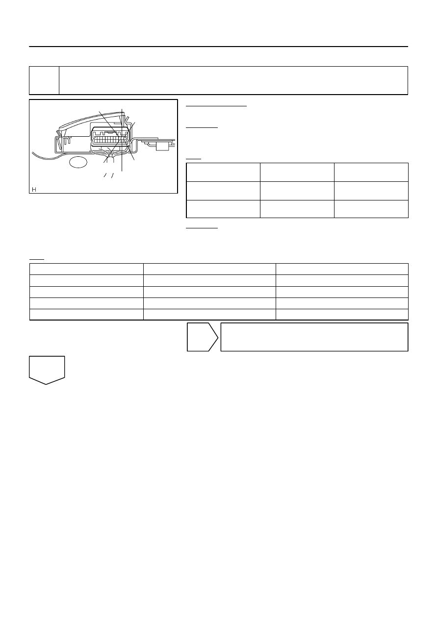
I28336
SGN1
HP1L
HP1R
SGN2
HP2R
R24
HP2L
DI–2074
–
DIAGNOSTICS
REAR SEAT AUDIO SYSTEM
2268
INSPECTION PROCEDURE
1
Inspect rear seat audio controller (Output signal).
PREPARATION:
Make sure that the rear seat audio connector is connected.
CHECK:
Measure the resistance according to the value(s) in the table
below.
OK:
Symbol
(Tester connection)
Condition
Specified condition
SGN1 (R24–1) – Body
ground
Always
Below 1
Ω
SGN2 (R24–13) – Body
ground
Always
Below 1
Ω
CHECK:
Check the waveform according to the condition(s) in the table
below.
OK:
Symbol (Tester connection)
Condition
Specified condition
HP1L (R24–2) – Body ground
Voice sound is being produced
A waveform synchronized with sound is output
HP1R (R24–3) – Body ground
Voice sound is being produced
A waveform synchronized with sound is output
HP2L (R24–14) – Body ground
Voice sound is being produced
A waveform synchronized with sound is output
HP2R (R24–15) – Body ground
Voice sound is being produced
A waveform synchronized with sound is output
NG
Replace rear seat audio controller.
OK
Нет комментариевНе стесняйтесь поделиться с нами вашим ценным мнением.
Текст