Toyota Sequoia (2005). Manual — part 567
I28299
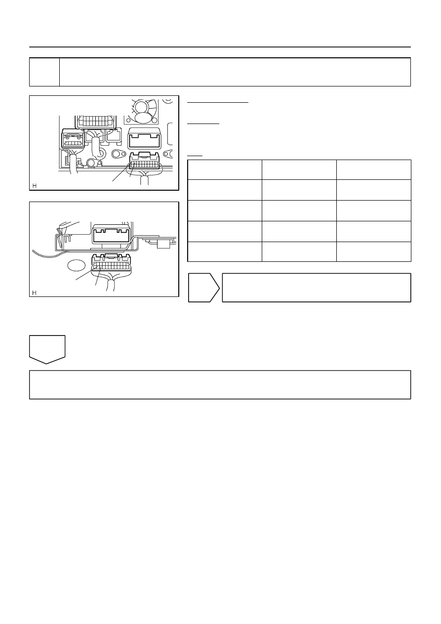
TX–
Radio and Navigation Assy
Wire Harness View:
TX+
R27
I28337
TX+
R24
TX–
Rear Seat Audio Controller
Wire Harness View:
–
DIAGNOSTICS
REAR SEAT AUDIO SYSTEM
DI–2063
2257
2
Check harness and connector (Rear seat audio controller – Radio and navigation
assy).
PREPARATION:
Disconnect the R24 and R27 connectors.
CHECK:
Measure the resistance according to the value(s) in the table
below.
OK:
Symbol
(Tester connection)
Condition
Specified condition
TX+ (R24–22) –
TX+ (R27–9)
Always
Below 1
Ω
TX– (R24–23) –
TX– (R27–10)
Always
Below 1
Ω
TX+ (R24–22) – Body
ground
Always
10 k
Ω
or higher
TX– (R24–23) – Body
ground
Always
10 k
Ω
or higher
NG
Repair or replace harness or connector.
OK
Replace rear seat audio controller.
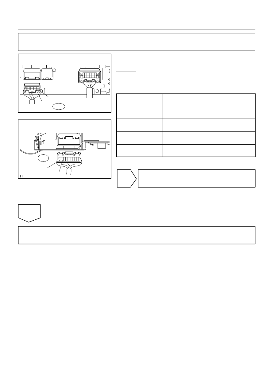
I28605
TX1+
R19
Radio Receiver Assy
Wire Harness View:
TX1–
I28337
TX+
R24
TX–
Rear Seat Audio Controller
Wire Harness View:
DI–2064
–
DIAGNOSTICS
REAR SEAT AUDIO SYSTEM
2258
3
Check harness and connector (Rear seat audio controller – Radio receiver assy).
PREPARATION:
Disconnect the R19 and R24 connectors.
CHECK:
Measure the resistance according to the value(s) in the table
below.
OK:
Symbol
(Tester connection)
Condition
Specified condition
TX+ (R24–22) –
TX1+ (R19–9)
Always
Below 1
Ω
TX– (R24–23) –
TX1– (R19–10)
Always
Below 1
Ω
TX+ (R24–22) – Body
ground
Always
10 k
Ω
or higher
TX– (R24–23) – Body
ground
Always
10 k
Ω
or higher
NG
Repair or replace harness or connector.
OK
Replace rear seat audio controller.
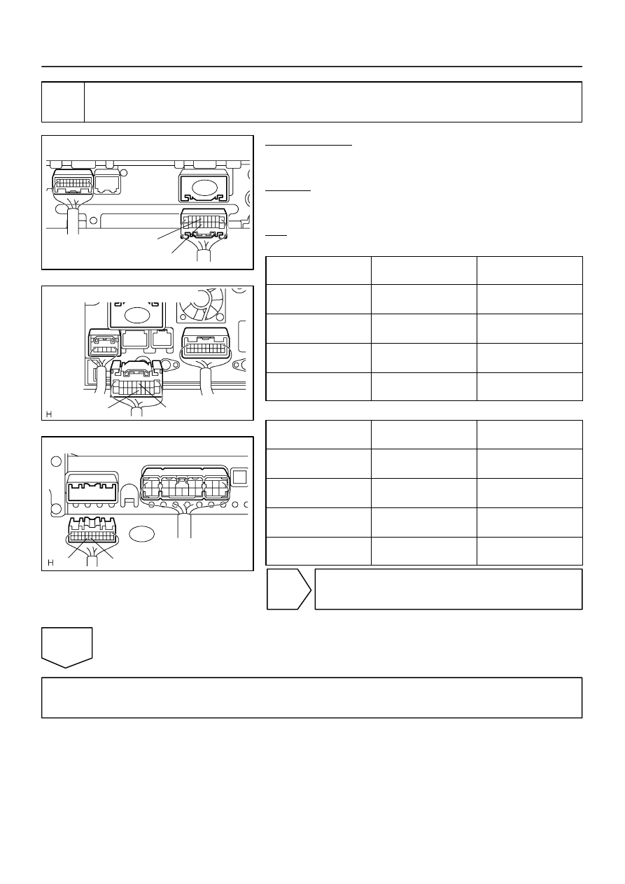
I28606
Radio Receiver Assy
Wire Harness View:
TX–
TX+
R4
I28292
TX+
Radio and Navigation Assy:
TX–
R30
I28752
Stereo Component Amplifier Assy :
S10
TX–
TX+
–
DIAGNOSTICS
REAR SEAT AUDIO SYSTEM
DI–2065
2259
4
Check harness and connector (Radio receiver assy / radio and navigation assy –
Stereo component amplifier assy).
PREPARATION:
Disconnect the radio receiver assy or radio and navigation assy
and stereo component amplifier assy connectors.
CHECK:
Measure the resistance according to the value(s) in the table
below.
OK:
Radio Receiver Assy:
Symbol
(Tester connection)
Condition
Specified condition
TX+ (R4–5) –
TX+ (S10–20)
Always
Below 1
Ω
TX– (R4–15) –
TX– (S10–19)
Always
Below 1
Ω
TX+ (R4–5) – Body
ground
Always
10 k
Ω
or higher
TX– (R4–15) – Body
ground
Always
10 k
Ω
or higher
Radio And Navigation Assy:
Symbol
(Tester connection)
Condition
Specified condition
TX+ (R30–5) –
TX+ (S10–20)
Always
Below 1
Ω
TX– (R30–15) –
TX– (S10–19)
Always
Below 1
Ω
TX+ (R30–5) – Body
ground
Always
10 k
Ω
or higher
TX– (R30–15) – Body
ground
Always
10 k
Ω
or higher
NG
Repair or replace harness or connector.
OK
Replace rear seat audio controller.
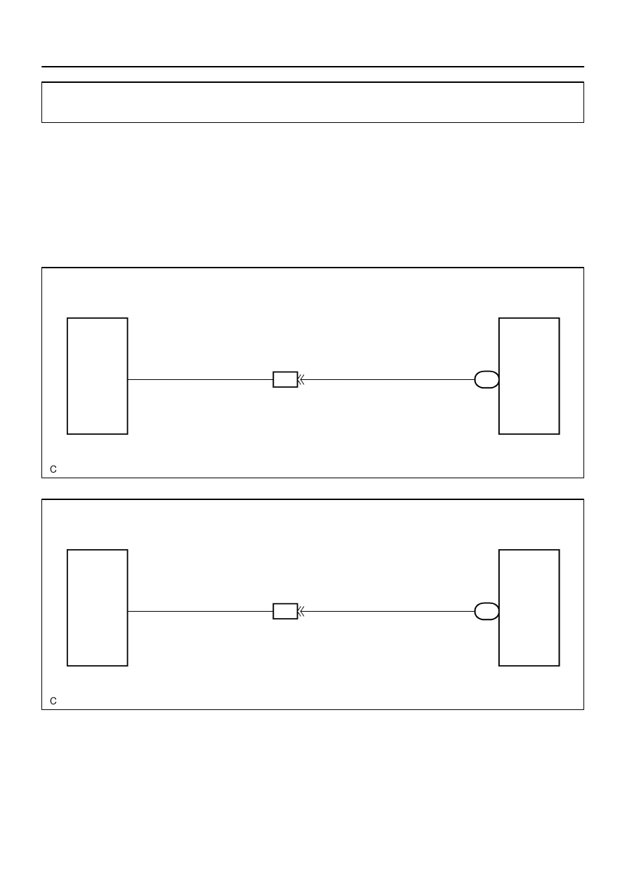
I28377
w/o Navigation System:
R19
Radio Receiver Assy
Rear Seat Audio Controller
RMUT
ID2
19
R24
11
RMU
11
LG
R–W
I28377
w/ Navigation System:
R27
Radio and Navigation Assy
Rear Seat Audio Controller
RMUT
ID2
19
R24
11
RMUT
11
LG
R–W
DI–2066
–
DIAGNOSTICS
REAR SEAT AUDIO SYSTEM
2260
Mute signal circuit (to rear seat audio controller)
CIRCUIT DESCRIPTION
This circuit sends the signal to the rear seat audio controller to mute the noise. Because of that, the noise
produced by changing the sound source ceases.
If there is an open in the circuit, noise can be heard from the speaker when changing the sound source.
If there is a short in the circuit, even though the rear seat audio controller is normal, no sound or only extreme-
ly small sound can be produced.
WIRING DIAGRAM
DIDAO–01
Нет комментариевНе стесняйтесь поделиться с нами вашим ценным мнением.
Текст