Toyota Sequoia (2005). Manual — part 166
–
DIAGNOSTICS
ENGINE
DI–459
653
8
Check whether DTC output recurs (DTC P2A00 or P2A03)
CHECK:
(a)
On the hand–held tester, select the following menu items: DIAGNOSIS / ENHANCED OBD II / DTC
INFO / PENDING CODES.
(b)
Read DTCs.
RESULT:
Display (DTC Output)
Proceed To
P2A00 or P2A03
A
No output
B
A
Check air–fuel ratio extremely lean or rich
(See page
B
END
0.02 inch orifice clogged
Pressure sensor low output
P043E
P043F
P0441
P0451
P0452
P0453
P0455
P0456
P2419
P2401
P2402
0.02 inch orifice high–flow
Pressure sensor stuck
Pressure sensor noise
Gross leak
Small leak
Vacuum pump stuck OFF
Vacuum pump stuck ON
Vent valve stuck closed
Vent valve stuck open (vent)
Purge VSV stuck open
Purge VSV stuck closed
Pressure sensor high output
DTCs
Malfunctioning Areas
P2420
P0450
DI–460
–
DIAGNOSTICS
ENGINE
654
EVAP (Evaporative Emission) Inspection Procedure
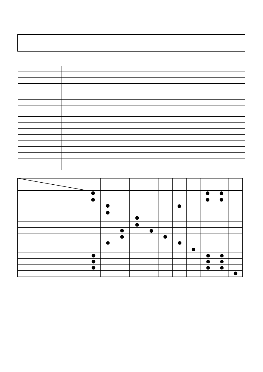
DTCS RELATING TO EVAP SYSTEM
DTCs
Monitoring Items
See Page
P043E
0.02 inch orifice clogged (built into pump module)
P043F
0.02 inch orifice high–flow (built into pump module)
P0441
Purge VSV
(Vacuum Switching Valve) stuck closed
Purge VSV
stuck open
Purge flow
P0450
Pressure sensor (built into pump module) voltage abnormal fluctuation
P0451
Pressure sensor (built into pump module) noising
Pressure sensor stuck (built into pump module)
P0452
Pressure sensor (built into pump module) voltage low
P0453
Pressure sensor (built into pump module) voltage high
P0455
EVAP gross leak
P0456
EVAP small leak
P2401
Vacuum pump stuck OFF (built into pump module)
P2402
Vacuum pump stuck ON (built into pump module)
P2419
Vent valve stuck closed (built into pump module)
P2420
Vent valve stuck open (vent) (built into pump module)
P2610
Soak timer (built into ECM)
If any EVAP system DTCs are set,
the malfunctioning area can be determined using the table below.
NOTICE:
If the 0.02 inch reference pressure difference between the first and second checks is greater than
the specification, the DTCs corresponding to the reference pressure (P043E, P043F, P0441, P0455,
P0456, P2401, P2420) will be all stored.
DIDFZ–01
A23474
Purge VSV
(Vacuum Switching Valve)
EVAP Hose
(To Throttle Body)
EVAP Hose
(From Canister)
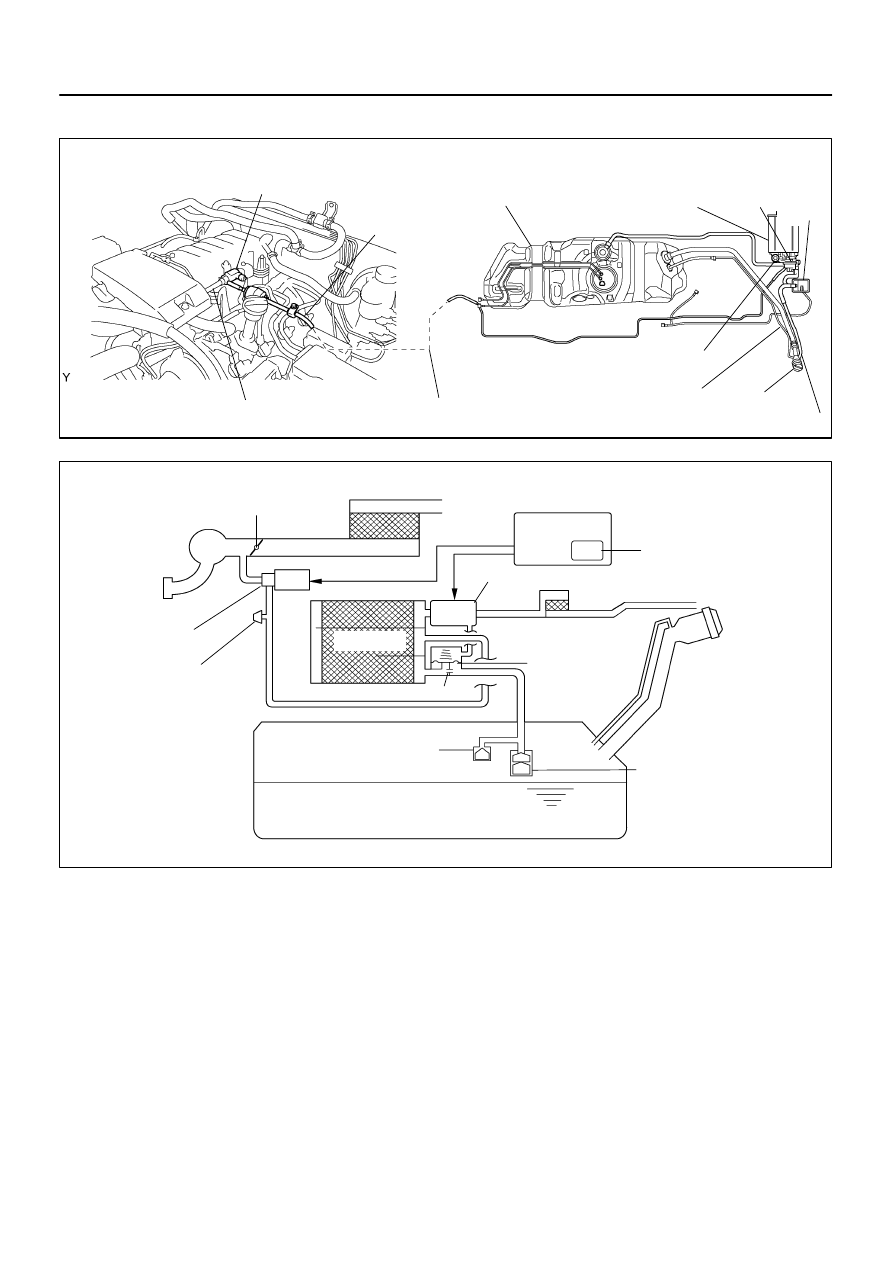
Location of EVAP (Evaporative Emission) system:
Vent Valve
Canister
Pressure Sensor
Vacuum Pump
Purge Line
Fuel Tank
Air Inlet Port
Breeding
Pipe
Fuel Tank Cap
Refueling Valve
Pump Module
Air Filter
A23668
EVAP System Circuit:
Intake Manifold
Purge VSV
Cut–Off Valve
Roll–Over Valve
Canister
Air Filter
fuel tank cap
Service Port
Air Cleaner
Restrictor (0.08 inch)
Refueling Valve
Throttle Valve
ECM
Soak Timer
Pump Module
Fuel Tank
–
DIAGNOSTICS
ENGINE
DI–461
655
CIRCUIT DESCRIPTION
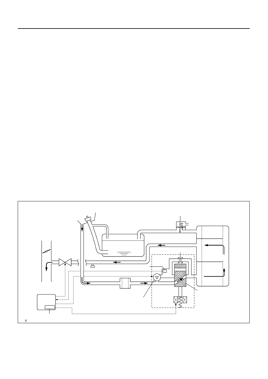
While the engine is running, if a predetermined condition (closed–loop, etc.) is met, the purge VSV is opened
by the ECM and stored fuel vapors in the canister are purged to the intake manifold. The ECM changes the
duty cycle ratio of the purge VSV to control purge flow volume.
The purge flow volume is also determined by the intake manifold pressure.
Atmospheric pressure is allowed
into the canister through the vent valve to ensure that the purge flow is maintained when the negative pres-
sure (vacuum) is applied to the canister.
The following two monitors run to confirm appropriate EVAP system operation.
A23669
EVAP Purge Flow:
Canister
Purge VSV
(ON)
Vacuum Pump (OFF)
Air Filter
Fuel Tank
fuel tank cap
To Intake Manifold
Pump Module
Pressure Sensor
0.02 Inch Orifice
Vent Valve (OFF)
ECM
Soak Timer
Refueling Valve
To Atmosphere
DI–462
–
DIAGNOSTICS
ENGINE
656
Key–off monitor
This monitor checks for EVAP (Evaporative Emission) system leaks and pump module malfunctions. The
monitor starts 5 hours*
after the ignition switch is turned OFF. More than 5 hours are required to allow enough
time for the fuel to cool down to stabilize the Fuel Tank Pressure (FTP), thus making the EVAP system moni-
tor more accurate.
The electric vacuum pump creates negative pressure (vacuum) in the EVAP system and the pressure is
measured. Finally, the ECM monitors for leaks from the EVAP system, and malfunctions in both the pump
module and purge VSV, based on the EVAP pressure.
HINT:
*:If the engine coolant temperature is not below 35
C 5 hours after the ignition switch is turned off, the moni-
tor check starts 2 hours later. If it is still not below 35
C 7 hours after the ignition switch is turned off, the
monitor check starts 2.5 hours later.
Purge flow monitor
The purge flow monitor consists of the two monitors. The 1st monitor is always conducted every time and
the 2nd monitor is activated if necessary.
The 1st monitor
While the engine is running and the purge VSV (Vacuum Switching Valve) is ON (open), the ECM
monitors the purge flow by measuring the EVAP pressure change. If negative pressure is not
created, the ECM begins the 2nd monitor.
The 2nd monitor
The vent valve is turned ON (closed) and the EVAP pressure is then measured. If the variation
in the pressure is less than 0.5 kpa (3.75 mmHg), the ECM interprets this as the purge VSV being
stuck closed, and illuminates the MIL and sets DTC P0441 (2 trip detection logic).
Atmospheric pressure check:
In order to ensure reliable malfunction detection, the variation between the atmospheric pressures, before
and after conduction of the purge flow monitor, is measured by the ECM.
Нет комментариевНе стесняйтесь поделиться с нами вашим ценным мнением.
Текст