Toyota Sequoia (2005). Manual — part 165
+25 %
–12.5 %
More than 3.35 V
Less than 3.0 V
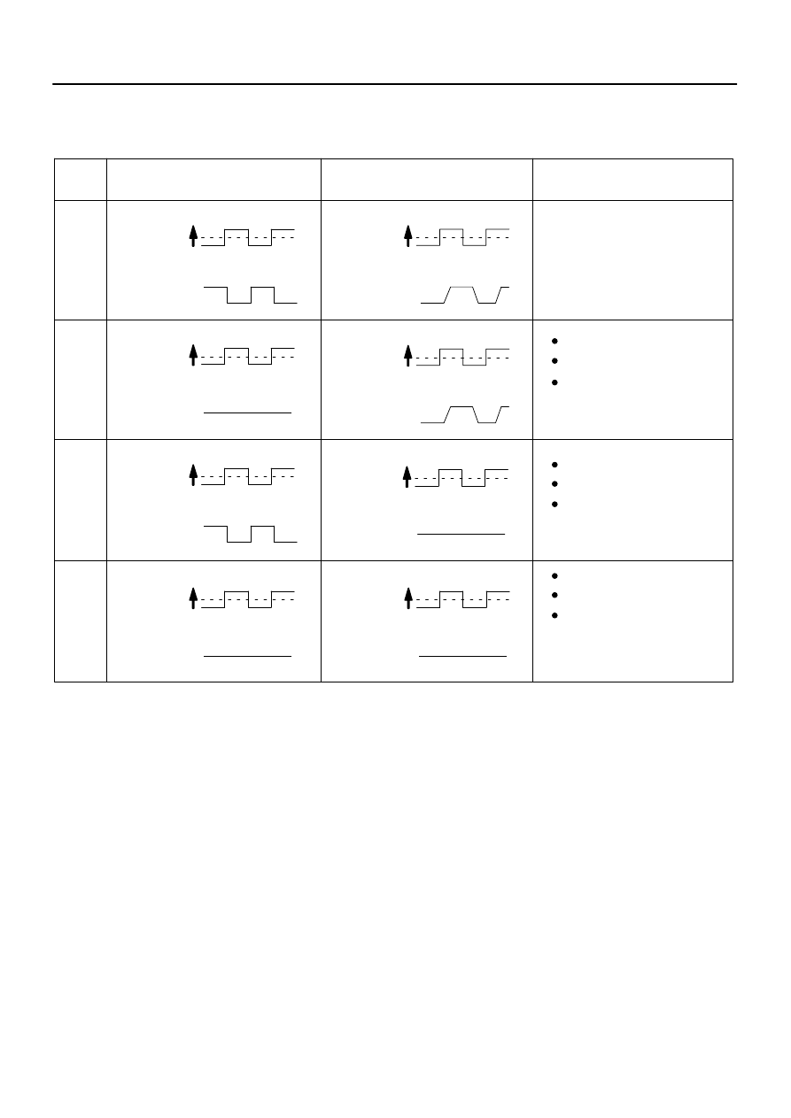
1
A/F Sensor (Sensor 1)
Output Voltage
Injection volume
Output voltage
HO2 Sensor (Sensor 2)
Output Voltage
Main Suspected
Trouble Areas
OK
+25 %
–12.5 %
More than 3.35 V
Less than 3.0V
Injection volume
Output voltage
+25 %
–12.5 %
More than 0.55 V
Less than 0.4V
Injection volume
Output voltage
A/F sensor
+25 %
–12.5 %
More than 0.55 V
Less than 0.4V
Injection volume
Output voltage
+25 %
–12.5 %
Injection volume
Output voltage
NG
+25 %
–12.5 %
Injection volume
Output voltage
NG
+25 %
–12.5 %
Injection volume
Output voltage
NG
+25 %
–12.5 %
Injection volume
Output voltage
NG
OK
OK
OK
Almost
no reaction
Almost
no reaction
Almost
no reaction
Almost
no reaction
Case
2
3
4
A/F sensor circuit
A/F sensor heater
HO2 sensor
HO2 sensor circuit
HO2 sensor heater
(Air–fuel ratio extremely
lean or rich)
Injector
Gas leakage from
exhaust system
Fuel pressure
–
DIAGNOSTICS
ENGINE
DI–455
649
NOTICE:
The Air–Fuel Ratio (A/F) sensor has an output delay of a few seconds and the Heated Oxygen (HO2)
sensor has a maximum output delay of approximately 20 seconds.
Following the A/F CONTROL procedure enables technicians to check and graph the voltage outputs
of both the A/F and HO2 sensors.
To display the graph, select the following menu items on the tester: DIAGNOSIS / ENHANCED OBD
II / ACTIVE TEST / A/F CONTROL / USER DATA / AFS B1S1 and O2S B1S2, and press the YES but-
ton and then the ENTER button followed by the F4 button.
HINT:
DTC P2A00 may be also set, when the air–fuel ratio is stuck rich or lean.
A low A/F sensor voltage could be caused by a rich air–fuel mixture. Check for conditions that would
cause the engine to run rich.
A high A/F sensor voltage could be caused by a lean air–fuel mixture. Check for conditions that would
cause the engine to run lean.
Read freeze frame data using a hand–held tester or OBD II scan tool. Freeze frame data record the
engine condition when malfunctions are detected. When troubleshooting, freeze frame data can help
determine if the vehicle was moving or stationary, if the engine was warmed up or not, if the air–fuel
ratio was lean or rich, and other data, from the time the malfunction occurred.
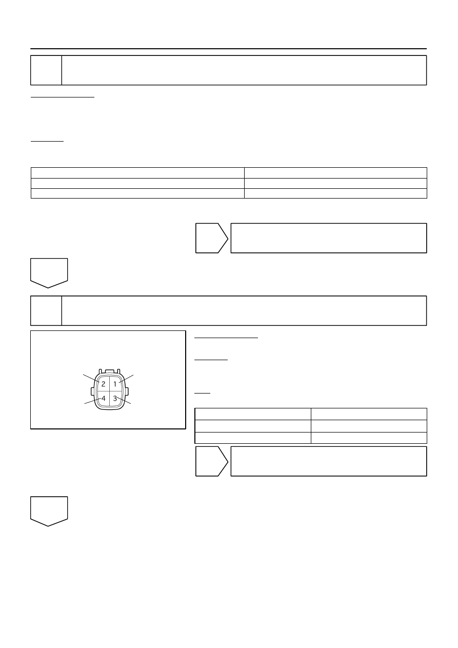
B17396
HT
+B
AF–
AF+
Sensor 1
A/F Sensor
Component Side:
Front View
DI–456
–
DIAGNOSTICS
ENGINE
650
1
Check any other DTCs output (in addition to DTC P2A00 or P2A03).
PREPARATION:
(a)
Connect a hand–held tester to the DLC3.
(b)
Turn the ignition switch to ON and turn the tester ON.
(c)
Select the following menu items: DIAGNOSIS / ENHANCED OBD II / DTC INFO / CURRENT CODES.
CHECK:
(a)
Read DTCs.
Result:
Display (DTC Output)
Proceed To
P2A00 and/or P2A03
A
P2A00 and/or P2A03 and other DTCs
B
HINT:
If any DTCs other than P2A00 and/or P2A03 are output, troubleshoot those DTCs first.
B
).
A
2
Check resistance of air–fuel ratio (A/F) sensor heater.
PREPARATION:
Disconnect the air–fuel ratio (A/F) sensor connector.
CHECK:
Measure resistance between the terminals of the A/F sensor
connector.
OK:
Standard:
Tester Connection
Specified Condition
HT (1) – +B (2)
Between 1.8
Ω
and 3.4
Ω
at 20
C (68
F)
HT (1) – AF– (4)
10 k
Ω
or higher
NG
Replace air–fuel ratio (A/F) sensor.
OK
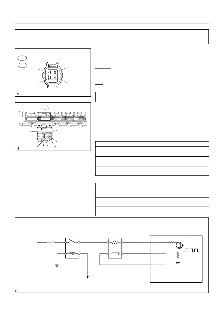
A23659
Wire Harness Side:
HT
A38
Sensor 1
A/F Sensor Connector
AF+
Front View
AF–
+B
A39
B17415
A55007
E7
ECM Connector
HA1A
A1A+
A1A–
A2A+
A2A–
HA2A
A23512
Reference (Bank 1 Sensor 1 System Drawing):
A/F Sensor
A/F Relay
Heater
Sensor
A1A+
HA1A
Duty
Control
ECM
From
Battery
A/F Heater
Fuse
A1A–
To EFI Relay
–
DIAGNOSTICS
ENGINE
DI–457
651
3
Check for open and short in harness and connector between ECM and A/F sen-
sor.
PREPARATION:
(a)
Disconnect the A38 or A39 A/F sensor connector.
(b)
Turn the ignition switch to ON.
CHECK:
(a)
Measure the voltage between the +B terminal of the A/F
sensor connector and body ground.
OK:
Standard:
Tester Connections
Specified Conditions
+B (2) – Body ground
Between 9 V and 14 V
PREPARATION:
(a)
Turn the ignition switch to OFF.
(b)
Disconnect the E7 ECM connector.
CHECK:
(a)
Check the resistance.
OK:
Standard (Check for open):
Tester Connections
Specified Conditions
HT (A38–1) – HA1A (E7–2)
HT (A39–1) – HA2A (E7–1)
Below 1
Ω
AF+ (A38–3) – A1A+ (E7–22)
AF+ (A39–3) – A2A+ (E7–23)
Below 1
Ω
AF– (A38–4) – A1A– (E7–30)
AF– (A39–4) – A2A– (E7–31)
Below 1
Ω
Standard (Check for short):
Tester Connections
Specified Conditions
HT (A38–1) or HA1A (E7–2) – Body ground
HT (A39–1) or HA2A (E7–1) – Body ground
10 k
Ω
or higher
AF+ (A38–3) or A1A+ (E7–22) – Body ground
AF+ (A39–3) or A2A+ (E7–23) – Body ground
10 k
Ω
or higher
AF– (A38–4) or A1A– (E7–30) – Body ground
AF– (A39–4) or A2A– (E7–31) – Body ground
10 k
Ω
or higher
DI–458
–
DIAGNOSTICS
ENGINE
652
NG
Replace or replace harness or connector.
OK
4
Perform confirmation driving pattern.
NEXT
5
Check whether DTC output recurs (DTC P2A00 or P2A03)
CHECK:
(a)
On the hand–held tester, select the following menu items: DIAGNOSIS / ENHANCED OBD II / DTC
INFO / PENDING CODES.
(b)
Read DTCs.
RESULT:
Display (DTC Output)
Proceed To
P2A00 or P2A03
A
No output
B
B
Check for intermittent problems
(See page
A
6
Replace air fuel ratio sensor.
NEXT
7
Perform confirmation driving pattern.
NEXT
Нет комментариевНе стесняйтесь поделиться с нами вашим ценным мнением.
Текст