Toyota Sequoia (2005). Manual — part 191
DIDIY–01
D14145
E8
E7
E6
E5
E4
–
DIAGNOSTICS
AUTOMATIC TRANSMISSION
DI–559
753
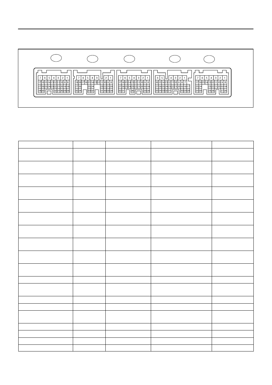
TERMINALS OF ECM
1.
ECM
HINT:
Each ECM terminal’s standard voltage is shown in the table below.
In the table, first follow the information under ”Condition”. Look under ”Symbols (Terminal No.)” for the termi-
nals to be inspected. The standard voltage between the terminals is shown under ”Specific Condition”.
Use the illustration above as a reference for the ECM terminals.
Symbols (Terminals No.)
Wiring Color
Terminal Description
Condition
Specified Condition
LMS (E5–9) – E1 (E6–1)
P–L – BR
L shift position switch sig-
nal
IG switch ON
10 to 14 V
↑
↑
↑
IG switch ON and Press continu-
ously shift position L switch
Below 1 V
2 (E5–10) – E1 (E6–1)
L – BR
2 shift position switch sig-
nal
IG switch ON and shift lever 2 and L
position
10 to 14 V
↑
↑
↑
IG switch ON and shift lever except
2 and L position
Below 1 V
R (E5–11) – E1 (E6–1)
B–Y – BR
R shift position switch sig-
nal
IG switch ON and shift lever R posi-
tion
10 to 14 V
↑
↑
↑
IG switch ON and shift lever except
R position
Below 1 V
D (E5–21) – E1 (E6–1)
W–R – BR
D shift position switch sig-
nal
IG switch ON and shift lever D and
4 position
10 to 14 V
↑
↑
↑
IG switch ON and shift lever except
D and 4 position
Below 1 V
3 (E5–19) – E1 (E6–1)
L – BR
3 shift position switch sig-
nal
IG switch ON and shift lever 3 posi-
tion
10 to 14 V
↑
↑
↑
IG switch ON and shift lever except
3 position
Below 1 V
ODMS (E4–12) – E1 (E6–1)
L–W – BR
O/D main switch signal
IG switch ON
10 to 14 V
↑
↑
↑
IG switch ON and press continu-
ously O/D main switch
Below 1 V
STP (E4–15) – E1 (E6–1)
G–Y – BR
Stop lamp switch signal
Brake pedal is depressed
7.5 to 14 V
↑
↑
↑
Brake pedal is released
Below 1.5 V
SLU+ (E7–15) – SLU– (E7–14)
P–L – L–W
SLU solenoid signal
5th (lock–up) gear
Pulse generation
(See waveform 2)
S2 (E7–10) – E1 (E6–1)
W–L – BR
S2 solenoid signal
2nd or 3rd gear
10 to 14 V
↑
↑
↑
1st, 4th or 5th gear
Below 1 V
S1 (E7–11) – E1 (E6–1)
R – BR
S1 solenoid signal
1st or 2nd gear
10 to 14 V
↑
↑
↑
3rd, 4th or 5th gear
Below 1 V
D14146
5 V/DIV
1 ms/DIV
GND
D14147
GND
5 V/DIV
1 ms/DIV
DI–560
–
DIAGNOSTICS
AUTOMATIC TRANSMISSION
754
SLT+ (E7–13) – SLT– (E7–12)
B–R – G–Y
SLT solenoid signal
Engine idle speed
Pulse generation
(See waveform 1)
SR (E7–9) – E1 (E6–1)
G–R – BR
SR solenoid signal
5th gear
10 to 14 V
↑
↑
↑
1st gear
Below 1 V
SL2+ (E7–17) – SL2– (E7–16)
GR – LG–B
SL2 solenoid signal
Engine idle speed
Pulse generation
(See waveform 3)
SL1+ (E7–19) – SL1– (E7–18)
R–B – L
SL1 solenoid signal
Engine idle speed
Pulse generation
(See waveform 4)
THO1 (E7–24) – E2 (E8–28)
G – G–W
No.1 ATF temperature
sensor signal
No.1 ATF temperature: 115
C (239
F) or more
Below 1.5 V
THO2 (E7–32) – E2 (E8–28)
V – G–W
No.2 ATF temperature
sensor signal
No.2 ATF temperature: 115
C (239
F) or more
Below 1.5 V
SP2+ (E7–34) – SP2– (E7–26)
W–R – Y–R
Speed sensor (SP2) sig-
nal
Vehicle speed 20 km/h (12 mph)
Pulse generation
(See waveform 6)
NT+ (E7–35) – NT– (E7–27)
B – W
Speed sensor (NT) signal
Engine idle speed
Pulse generation
(See waveform 5)
STAR/NSW (E7–8) – E1 (E6–1)
B – BR
Park neutral switch signal
IG switch ON and shift lever P and
N position
Below 2 V
↑
↑
↑
IG switch ON and shift lever except
P and N position
10 to 14 V
L4* (E6–13) – E1 (E6–1)
L–R – BR
Transfer L position switch
signal
IG switch ON and transfer L posi-
tion
Below 1 V
↑
↑
↑
IG switch ON and transfer except L
position
10 to 14 V
HINT:
*: 4WD
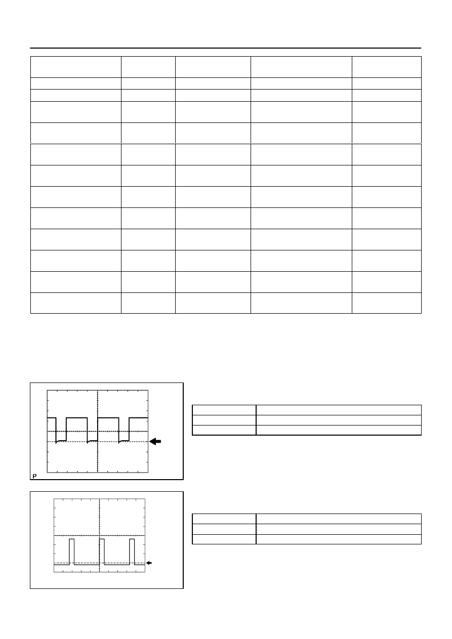
Waveform 1
Reference:
Terminal
SLT+ – SLT–
Tool setting
5V/DIV, 1ms/DIV
Vehicle condition
Engine idle speed
Waveform 2
Reference:
Terminal
SLU+ – SLU–
Tool setting
5V/DIV, 1ms/DIV
Vehicle condition
5th (lock–up) or 6th (lock–up) gear
D14146
5 V/DIV
1 ms/DIV
GND
D14146
5 V/DIV
1 ms/DIV
GND
D14148
GND
1 V/DIV
2 ms/DIV
C13480
D14149
GND
2 V/DIV
20 ms/DIV
–
DIAGNOSTICS
AUTOMATIC TRANSMISSION
DI–561
755
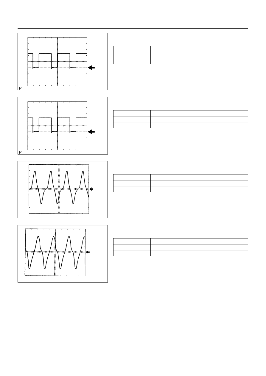
Waveform 3
Reference:
Terminal
SL2+ – SL2–
Tool setting
5V/DIV, 1ms/DIV
Vehicle condition
Engine idle speed
Waveform 4
Reference:
Terminal
SL1+ – SL1–
Tool setting
5V/DIV, 1ms/DIV
Vehicle condition
Engine idle speed
Waveform 5
Reference:
Terminal
NT+ – NT–
Tool setting
1V/DIV, 2ms/DIV
Vehicle condition
Engine idle speed (P or N position)
Waveform 6
Reference:
Terminal
SP2+ – SP2–
Tool setting
2V/DIV, 20ms/DIV
Vehicle condition
Vehicle speed 20 km/h (12 mph)
DIDIZ–01
D14150
D13872
DLC3
OBD II Scan Tool
(Hand–held Tester)
CAN VIM
D14151
DLC3
1314 1516
12
11
10
9
1 2 3 4 5 6 7 8
DI–562
–
DIAGNOSTICS
AUTOMATIC TRANSMISSION
756
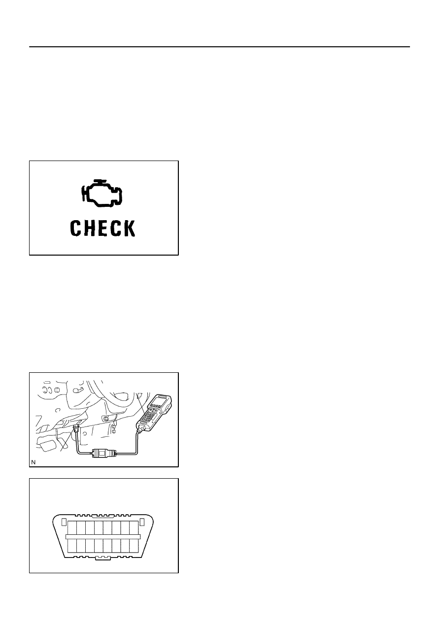
DIAGNOSIS SYSTEM
DESCRIPTION
When troubleshooting On–Board Diagnostic (OBD II) vehicles,
the vehicle must be connected to the OBD II scan tool (comply-
ing with SAE J1987). Various data output from the vehicle’s
ECM can then be read.
OBD II regulations require that the vehicle’s on–board comput-
er illuminates the Malfunction Indicator Lamp (MIL) on the
instrument panel when the computer detects a malfunction in:
1) The emission control system/components
2) The powertrain control components (which affect vehicle
emissions)
3) The computer
In addition, the applicable Diagnostic Trouble Codes (DTCs)
prescribed by SAE J2012 are recorded in the ECM memory.
If the malfunction does not reoccur in 3 consecutive trips, the
MIL turns off automatically but the DTCs remain recorded in the
ECM memory.
To check DTCs, connect the scan tool to the Data Link Connec-
tor 3 (DLC3) of the vehicle. The scan tool displays DTCs, the
freeze frame data and a variety of the engine data.
The DTCs and freeze frame data can be erased with the scan
tool (See page
NORMAL MODE AND CHECK MODE
The diagnosis system operates in ”normal mode” during normal
vehicle use. In normal mode, ”2–trip detection logic” is used to
ensure accurate detection of malfunctions. ”Check mode” is
also available to technicians as an option. In check mode,
”1–trip detection logic” is used for simulating malfunction symp-
toms and increasing the system’s ability to detect malfunctions,
including intermittent malfunctions.
2–TRIP DETECTION LOGIC
When a malfunction is first detected, the malfunction is tempo-
rarily stored in the ECM memory (1st trip). If the ignition switch
is turned OFF and then ON again, and the same malfunction is
detected again, the MIL will illuminate.
Нет комментариевНе стесняйтесь поделиться с нами вашим ценным мнением.
Текст