Toyota Sequoia (2005). Manual — part 192
D14152
DTC was set.
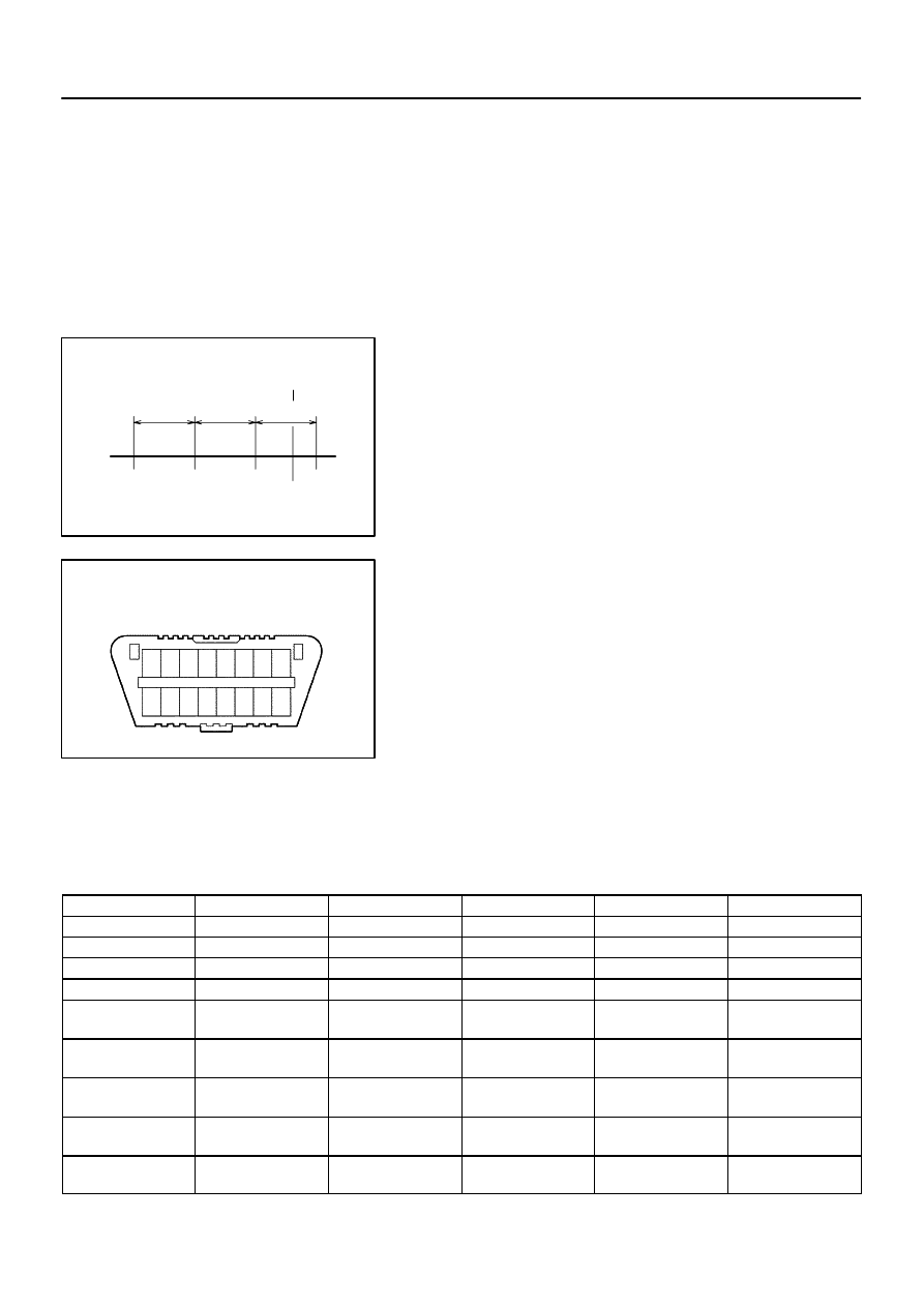
0.5 sec. 0.5 sec. 0.5 sec.
: Freeze frame data which can be read
D14151
DLC3
1314 1516
12
11
10
9
1 2 3 4 5 6 7 8
–
DIAGNOSTICS
AUTOMATIC TRANSMISSION
DI–563
757
FREEZE FRAME DATA
Freeze frame data records the engine conditions (fuel system,
calculated load, engine coolant temperature, fuel trim, engine
speed, vehicle speed, etc.) when a malfunction is detected.
When troubleshooting, freeze frame data can help determine
if the vehicle was running or stopped, if the engine was warmed
up or not, if the air/fuel ratio was Lean or Rich, and other data
from the time the malfunction occurred.
The hand–held tester records freeze frame data in five different
instances: 1) 3 times before the DTC is set, 2) once when the
DTC is set, and 3) once after the DTC is set. These data can be
used to simulate the vehicle’s condition around the time when
the malfunction occurred. The data may help find the cause of
the malfunction, or judge if the DTC is being caused by a tempo-
rary malfunction or not.
DLC3 (Data Link Connector 3)
The vehicle’s ECM uses the ISO 15765–4 for communication
protocol. The terminal arrangement of the DLC3 complies with
SAE J1962 and matches the ISO 15765–4 format.
HINT:
Connect the cable of the hand–held tester to the DLC3, turn the
ignition switch ON and attempt to use the hand–held tester. If
the screen displays UNABLE TO CONNECT TO VEHICLE, a
problem exists in the vehicle side or the tester side.
If the communication is normal when the tool is connected to
another vehicle, inspect the DLC3 on the original vehicle.
If the communication is still impossible when the tool is con-
nected to another vehicle, the problem is probably in the tool it-
self. Consult the Service Department listed in the tool’s instruc-
tion manual.
Symbol
Terminal No.
Name
Reference terminal
Result
Condition
SIL
7
Bus ”+” line
5 – Signal ground
Pulse generation
During transmission
CG
4
Chassis ground
Body ground
Below 1
Ω
Always
SG
5
Signal ground
Body ground
Below 1
Ω
Always
BAT
16
Battery positive
Body ground
11 to 14 V
Always
CANH
6
HIGH–level CAN
bus line
CANL
54 to 69
Ω
IG switch OFF
CANH
6
HIGH–level CAN
bus line
Battery positive
1 M
Ω
or higher
IG switch OFF
CANH
6
HIGH–level CAN
bus line
CG
1 k
Ω
or higher
IG switch OFF
CANL
14
LOW–level CAN
bus line
Battery positive
1 M
Ω
or higher
IG switch OFF
CANL
14
LOW–level CAN
bus line
CG
1 k
Ω
or higher
IG switch OFF
DI–564
–
DIAGNOSTICS
AUTOMATIC TRANSMISSION
758
CHECK BATTERY VOLTAGE
Battery voltage: 11 to 14 V
If voltage is below 11 V, replace the battery before proceeding.
CHECK MIL
(a)
Check that the MIL illuminates when turning the ignition
switch ON.
If the MIL does not illuminate, there is a problem in the MIL cir-
cuit (refer to MIL CIRCUIT on page
)
(b)
When the engine is started, the MIL should turn off.
ALL READINESS
For this vehicle, using the hand–held tester allows readiness
codes corresponding to all DTCs to be read. When diagnosis
(normal or malfunctioning) has been complete, readiness
codes are set. Enter the following menus: ENHANCED OBD II
/ MONITOR STATUS on the hand–held tester.
DIDJ0–01
D13872
DLC3
OBD II Scan Tool
(Hand–held Tester)
CAN VIM
–
DIAGNOSTICS
AUTOMATIC TRANSMISSION
DI–565
759
DTC CHECK / CLEAR
1.
CHECK DTC
DTCs which are stored in the ECM can be displayed with the
hand–held tester or generic OBD II scan tool.
These scan tools can display pending DTCs and current DTCs.
Some DTC aren’t stored if the ECM doesn’t detect a malfunc-
tion during consecutive driving. However, the detected mal-
function during once driving is stored as pending DTC.
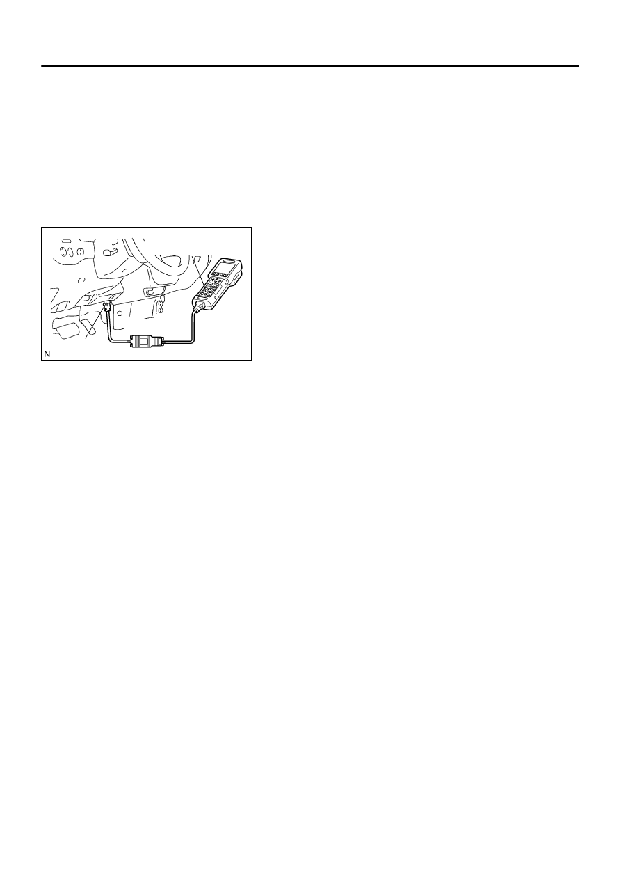
(a)
Connect the hand–held tester to the Controller Area Net-
work Vehicle Interface Module (CAN VIM). Then connect
the CAN VIM to the Data Link Connector 3 (DLC3).
(b)
Turn the ignition switch ON.
(c)
Enter the following menus: DIAGNOSIS / ENHANCED
OBD II / DTC INFO / CURRENT CODES (or PENDING
CODE).
(d)
Confirm the DTCs and freeze frame data and then write
them down.
(e)
to confirm the details of the DTCs.
NOTICE:
When simulating a symptom with the scan tool to check for
DTCs, use normal mode. For codes on DIAGNOSTIC
TROUBLE CODE CHART subject to ”2–trip detection log-
ic”, perform the following actions.
Turn the ignition switch OFF after the symptom is simulated
once. Then repeat the simulation process again. When the
problem has been simulated twice, the MIL illuminates and the
DTCs are recorded in the ECM.
2.
CLEAR DTC
(a)
Connect the hand–held tester to the CAN VIM. Then con-
nect the CAN VIM to the DLC3.
(b)
Turn the ignition switch ON.
(c)
Enter the following menus: DIAGNOSIS / ENHANCED
OBD II / DTC INFO / CLEAR CODES and press YES.
DIDJ1–01
D13872
DLC3
OBD II Scan Tool
(Hand–held Tester)
CAN VIM
D14153
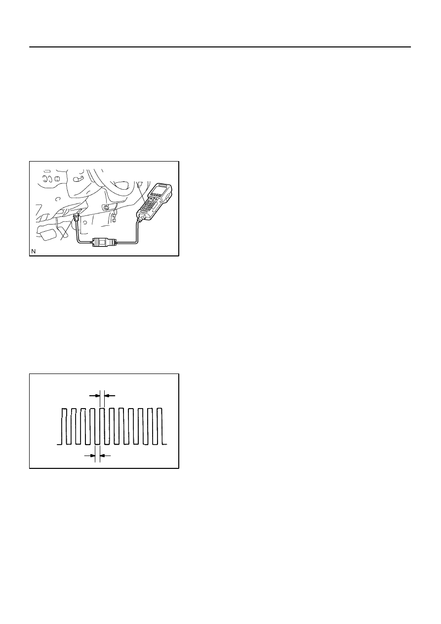
ON
OFF
0.13 seconds
0.13 seconds
DI–566
–
DIAGNOSTICS
AUTOMATIC TRANSMISSION
760
CHECK MODE PROCEDURE
DESCRIPTION
Check mode has a higher sensitivity to malfunctions and can
detect malfunctions that normal mode cannot detect. Check
mode can also detect all the malfunctions that normal mode can
detect. In check mode, DTCs are detected with 1–trip detection
logic.
CHECK MODE PROCEDURE
(a)
Make sure that the items below are true:
(1)
Battery positive voltage 11 V or more
(2)
Throttle valve fully closed
(3)
Transmission in the P or N position
(4)
A/C switched OFF
(b)
Turn the ignition switch OFF.
(c)
Connect the hand–held tester together with the Controller
Area Network Vehicle Interface Module (CAN VIM) to the
DLC3.
(d)
Turn the ignition switch ON.
(e)
Enter the following menus: DIAGNOSIS / ENHANCED
OBD II / CHECK MODE.
(f)
Change the ECM to check mode. Make sure the MIL
flashes as shown in the illustration.
NOTICE:
All DTCs and freeze frame data recorded will be erased if:
1) the hand–held tester is used to change the ECM from
normal mode to check mode or vice–versa; or 2) during
check mode, the ignition switch is turned from ON to ACC
or LOCK.
Before check mode, make notes of the DTCs and freeze
frame data.
(g)
Start the engine. The MIL should turn off after the engine
starts.
(h)
Perform ”MONITOR DRIVE PATTERN” for the ECT test
(See page
(Or, simulate the conditions of the malfunction described
by the customer).
(i)
After simulating the malfunction conditions, use the
hand–held tester diagnosis selector to check the DTC
and freeze frame data.
Нет комментариевНе стесняйтесь поделиться с нами вашим ценным мнением.
Текст