Toyota Sequoia (2005). Manual — part 201
D14165
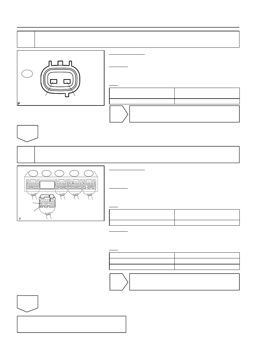
Sensor Side:
(Connector Front View):
2
1
V2
D14166
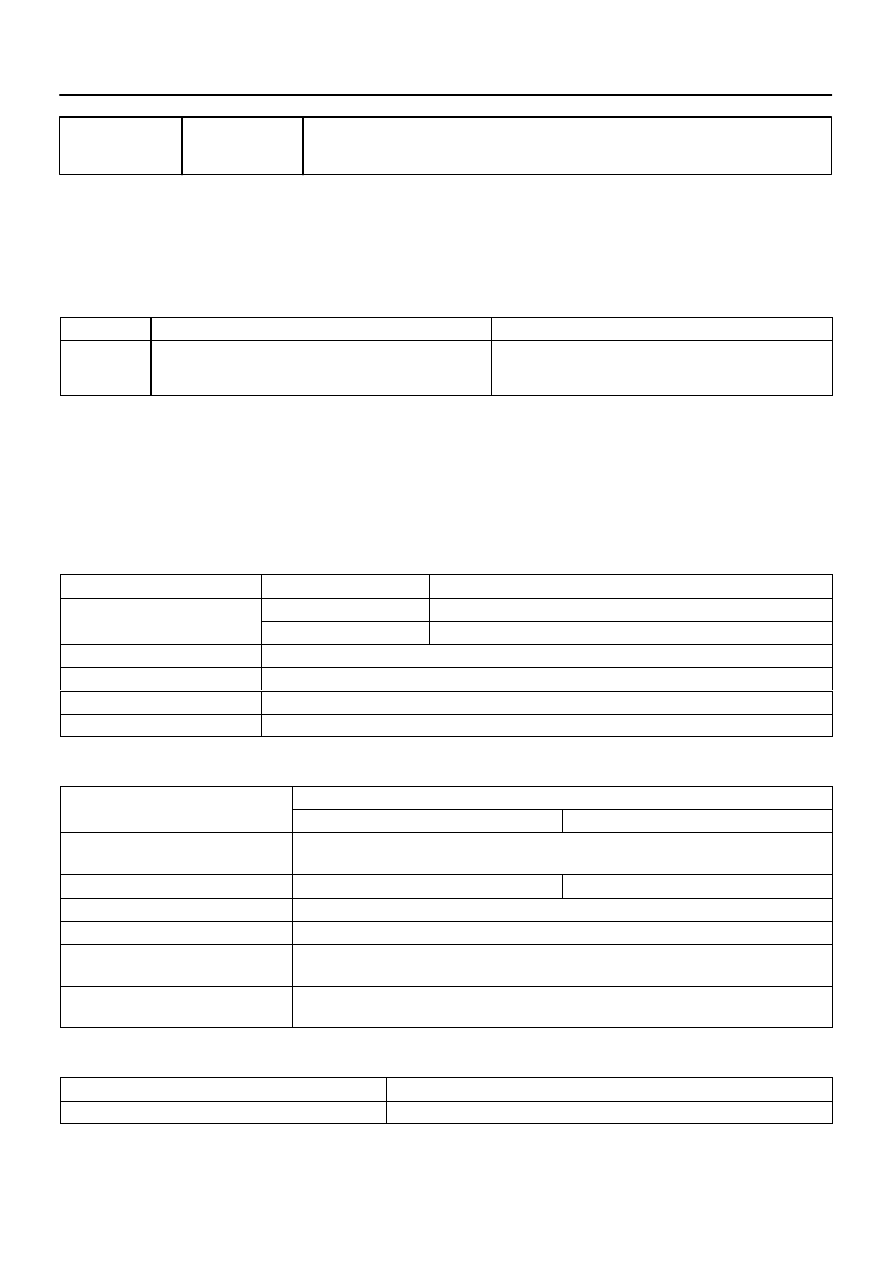
ECM:
SP2+
SP2–
E8
E7
E6
E5
E4
–
DIAGNOSTICS
AUTOMATIC TRANSMISSION
DI–599
793
2
Inspect speed sensor SP2.
PREPARATION:
Disconnect the speed sensor connector from the transmission.
CHECK:
Measure the resistance according to the value(s) in the table
below.
OK:
Tester Connection
Specified Condition
20
C (68
F)
1 – 2
560 to 680
Ω
NG
Replace speed sensor SP2 (See page
OK
3
Check harness and connector (ECM – speed sensor SP2).
PREPARATION:
(a)
Connect the speed sensor connector.
(b)
Disconnect the ECM connector.
CHECK:
Measure the resistance according to the value(s) in the table
below.
OK:
Tester Connection
Specified Condition
20
C (68
F)
E7 – 34 (SP2+) – E7 – 26 (SP2–)
560 to 680
Ω
CHECK:
Measure the resistance according to the value(s) in the table
below.
OK:
Tester Connection
Specified Condition
E7 – 34 (SP2+) – Body ground
10 k
Ω
or higher
E7 – 26 (SP2–) – Body ground
↑
NG
Repair or replace the harness or connector
(See page
).
OK
Replace the ECM (See page
DI–600
–
DIAGNOSTICS
AUTOMATIC TRANSMISSION
794
DTC
P0724
Brake Switch ”B” Circuit High
CIRCUIT DESCRIPTION
The purpose of this circuit is to prevent the engine from stalling while driving in lock–up condition when
brakes are suddenly applied.
When the brake pedal is depressed, this switch sends a signal to the ECM. Then the ECM cancels the opera-
tion of the lock–up clutch while braking is in progress.
DTC No.
DTC Detection Condition
Trouble Area
P0724
The stop light switch remains ON even when the vehicle is
driven in a STOP (less than 3 km/h (2 mph)) and GO (30 km/h
(19 mph) or more) fashion 5 times. (2–trip detection logic).
Short in stop light switch signal circuit
Stop light switch
ECM
MONITOR DESCRIPTION
This DTC indicates that the stop light switch remains on. When the stop light switch remains ON during ”stop
and go” driving, the ECM interprets this as a fault in the stop light switch and the MIL comes on and the ECM
stores the DTC. The vehicle must stop (less than 3 km/h (2 mph)) and go (30 km/h (19 mph) or more) ten
times for two driving cycles in order to detect a malfunction.
MONITOR STRATEGY
Related DTCs
P0724
Stop light switch/Range check/Rationality
R
i d
/C
t
Main
Stop light switch
Required sensors/Components
Sub
Vehicle speed sensor
Frequency of operation
Continuous
Duration
GO and STOP 5 times
MIL operation
2 driving cycles
Sequence of operation
None
TYPICAL ENABLING CONDITIONS
It
Specification
Item
Minimum
Maximum
The monitor will run whenever this DTC is
not present.
See page
Battery voltage
8 V or more
–
Ignition switch
ON
Starter
OFF
GO (Vehicle speed is 30 km/h
(18.63 mph) or more)
Once
STOP (Vehicle speed is less than 3 km/h
(1.86 mph))
Once
TYPICAL MALFUNCTION THRESHOLDS
Detection criteria
Threshold
Brake switch
Remain ON during GO and STOP 5 times
DIDJA–01
–
DIAGNOSTICS
AUTOMATIC TRANSMISSION
DI–601
795
WIRING DIAGRAM
See page
INSPECTION PROCEDURE
1
Read value of DATA LIST (STP signal).
HINT:
According to the DATA LIST displayed by the OBD II scan tool or hand–held tester, you can read the value
of the switch, sensor, actuator and so on without parts removal. Reading the DATA LIST as the first step of
troubleshooting is one method to shorten labor time.
(a)
Warm up the engine.
(b)
Turn the ignition switch off.
(c)
Connect the OBD II scan tool or hand–held tester to the DLC3.
(d)
Turn the ignition switch to the ON position.
(e)
Push the ”ON” button of the OBD II scan tool or the hand–held tester.
(f)
When you use the hand–held tester:
Select the item ”DIAGNOSIS / ENHANCED OBD II / DATA LIST”.
(g)
According to the display on the tester, read the ”DATA LIST”.
Standard:
Item
Measurement Item/
Range (display)
Normal Condition
Stop Light Switch
Stop light SW Status/
ON or OFF
Brake Pedal is depressed: ON
Brake Pedal is released: OFF
NOTICE:
In the table above, the conditions listed under ”Normal Condition” are reference conditions. Do not
depend solely on these reference conditions when deciding whether a part is faulty or not.
OK:
Brake Pedal Condition
Specified Condition
Depressed
ON
Released
OFF
NG
Go to step 2.
OK
Go to step 3.
I21525
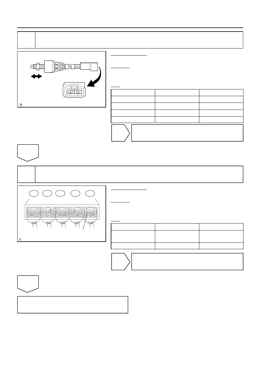
Free
Pushed in
D14167
ECM:
E8
E7
E6
E5
E4
STP(+)
DI–602
–
DIAGNOSTICS
AUTOMATIC TRANSMISSION
796
2
Inspect stop light switch.
PREPARATION:
Remove the stop lamp switch assy.
CHECK:
Measure the resistance according to the value(s) in the table
below.
OK:
Switch position
Tester Connection
Specified Condition
Switch pin free
1 – 4
Below 1
Ω
Switch pin pushed in
↑
10 k
Ω
or higher
Switch pin free
2 – 3
10 k
Ω
or higher
Switch pin pushed in
↑
Below 1
Ω
NG
Replace stop light switch (See page
OK
3
Check harness and connector (ECM – stop light switch).
PREPARATION:
Install the stop lamp switch assy.
CHECK:
Measure the voltage according to the value(s) in the table be-
low when the brake pedal is depressed and released.
OK:
Condition
Tester Connection
Specified Condition
Brake pedal is depressed
E4 – 15 (STP) –
Body ground
10 to 14 V
Brake pedal is released
↑
Below 1 V
NG
Repair or replace the harness or connector
(See page
).
OK
Replace the ECM (See page
Нет комментариевНе стесняйтесь поделиться с нами вашим ценным мнением.
Текст