Toyota Sequoia (2005). Manual — part 353
C84207
G27650
H43694
H24002
Occupant
Classification ECU
Airbag
Sensor
Assembly
D
FSR–
FSR+
C
B
A
FSR+
FSR–
O6
E
F
A21
Service Wire
C84205
G27650
H24003
Occupant
Classification ECU
Airbag
Sensor
Assembly
D
A21
FSR–
FSR+
C
B
A
E
F
–
DIAGNOSTICS
SUPPLEMENTAL RESTRAINT SYSTEM
DI–1207
1401
5
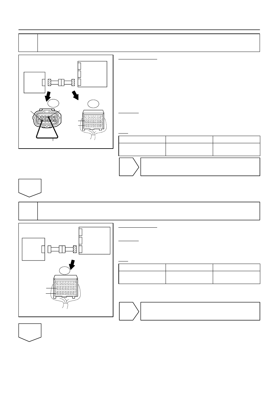
Check occupant classification system circuit (open).
PREPARATION:
(a)
Disconnect the connector from the occupant classifica-
tion ECU.
(b)
Using a service wire, connect O6–8 (FSR+) and O6–4
(FSR–) of connector ”E”.
NOTICE:
Do not forcibly insert a service wire into the terminals of the
connector when connecting.
CHECK:
Measure the resistance according to the value(s) in the table
below.
OK:
Tester Connection
Condition
Specified Condition
A21–16 (FSR+) –
A21–24 (FSR–)
Always
Below 1
Ω
NG
Go to step 9.
OK
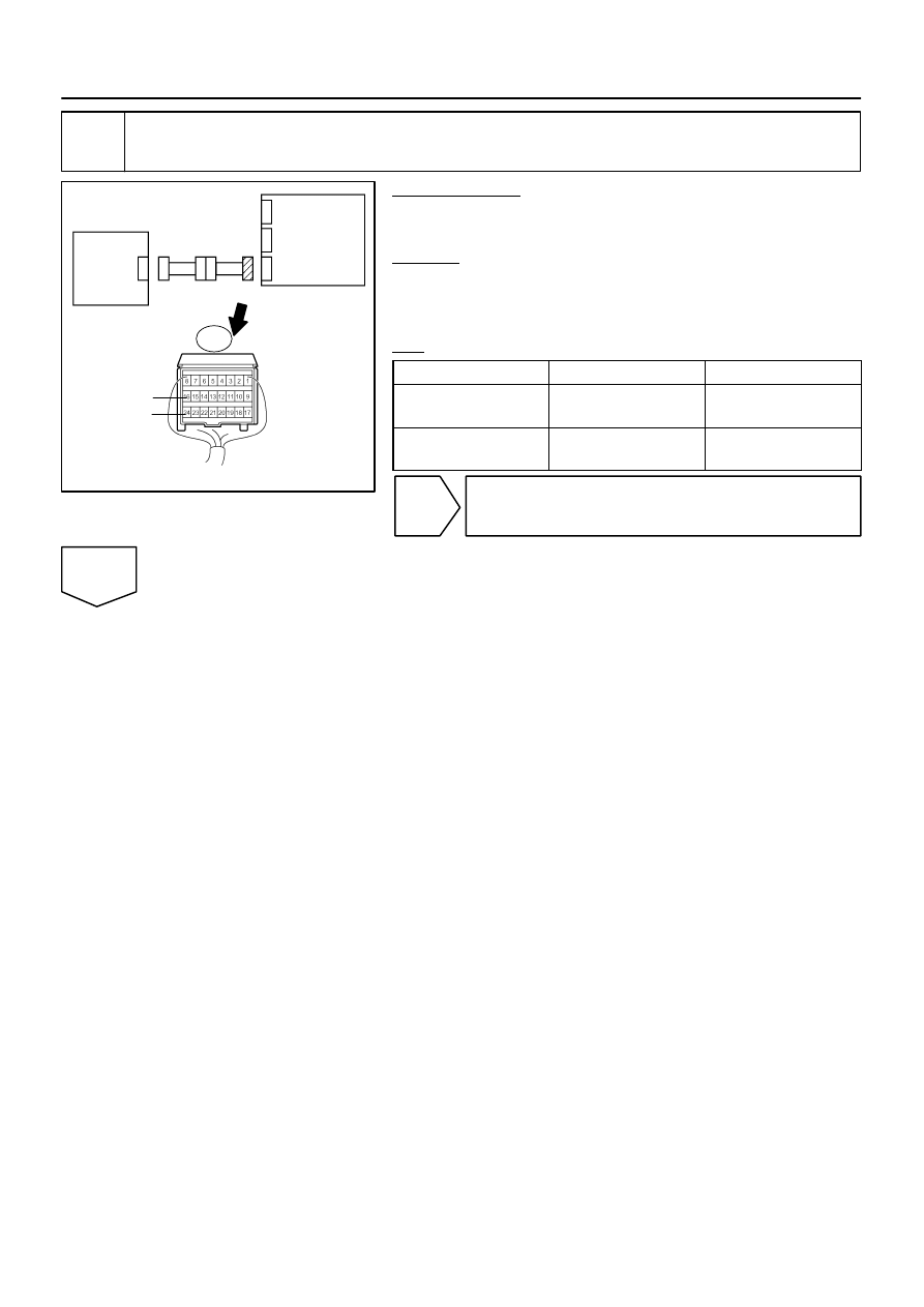
6
Check occupant classification system circuit (short).
PREPARATION:
Disconnect the service wire from connector ”E”.
CHECK:
Measure the resistance according to the value(s) in the table
below.
OK:
Tester Connection
Condition
Specified Condition
A21–16 (FSR+) –
A21–24 (FSR–)
Always
1 M
Ω
or higher
NG
Go to step 10.
OK
C84205
G27650
H24003
Occupant
Classification ECU
Airbag
Sensor
Assembly
D
A21
FSR–
FSR+
C
B
A
E
F
DI–1208
–
DIAGNOSTICS
SUPPLEMENTAL RESTRAINT SYSTEM
1402
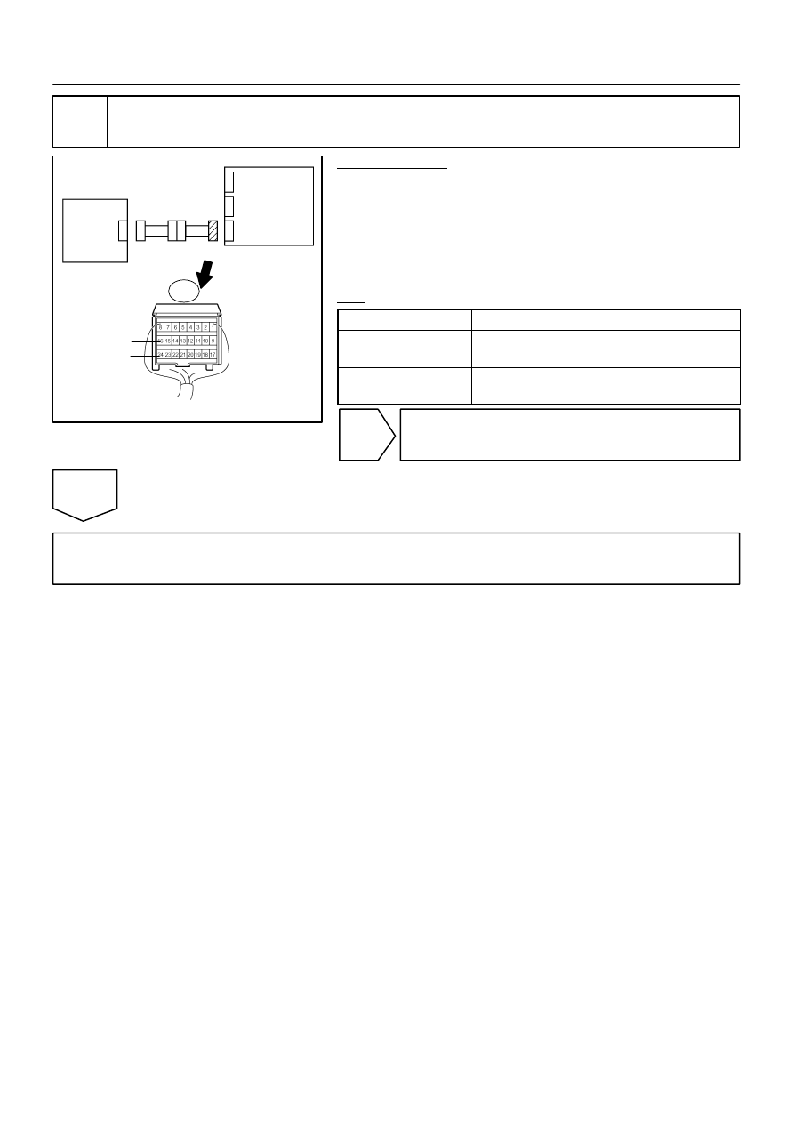
7
Check occupant classification system circuit (short to B+).
PREPARATION:
Connect the negative (–) terminal cable to the battery, and wait
for at least 2 seconds.
CHECK:
(a)
Turn the ignition switch to the ON position.
(b)
Measure the resistance according to the value(s) in the
table below.
OK:
Tester Connection
Condition
Specified Condition
A21–16 (FSR+) –
Body ground
Ignition switch ON
Below 1 V
A21–24 (FSR–) –
Body ground
Ignition switch ON
Below 1 V
NG
Go to step 11.
OK
C84205
G27650
H24003
Occupant
Classification ECU
Airbag
Sensor
Assembly
D
A21
FSR–
FSR+
C
B
A
E
F
–
DIAGNOSTICS
SUPPLEMENTAL RESTRAINT SYSTEM
DI–1209
1403
8
Check occupant classification system circuit (short to ground).
PREPARATION:
(a)
Turn the ignition switch to the LOCK position.
(b)
Disconnect the negative (–) terminal cable from the bat-
tery, and wait for at least 90 seconds.
CHECK:
Measure the resistance according to the value(s) in the table
below.
OK:
Tester Connection
Condition
Specified Condition
A21–16 (FSR+) –
Body ground
Always
1 M
Ω
or higher
A21–24 (FSR–) –
Body ground
Always
1 M
Ω
or higher
NG
Go to step 12.
OK
Replace airbag sensor assembly (see page
).
HINT:
Check for DTCs of the airbag sensor assembly. If the DTC B1650/32 is detected, replace the occupant clas-
sification ECU (see page
) and perform a ”Zero point calibration” and ”Sensitivity check” of the occu-
pant classification system (see page
C84213
H43694 H24024
H24004
Occupant
Classification
ECU
Airbag
Sensor
Assembly
A
O6
FSR+
FSR–
B
C
D
E
F
Service Wire
BL1
Seat Wire No. 1
Floor Wire
FSR+
FSR–
C84211
H24024
H24005
Occupant
Classification
ECU
Airbag
Sensor
Assembly
A
FSR+
FSR–
B
C
D
E
F
BL1
Seat Wire No. 1
Floor Wire
DI–1210
–
DIAGNOSTICS
SUPPLEMENTAL RESTRAINT SYSTEM
1404
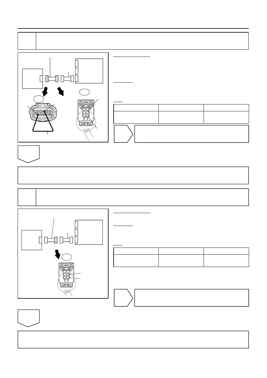
9
Check seat wire No. 1 (open).
PREPARATION:
Disconnect the seat wire No. 1 connector from the floor wire.
HINT:
The service wire has already been inserted into connector ”E”.
CHECK:
Measure the resistance according to the value(s) in the table
below.
OK:
Tester Connection
Condition
Specified Condition
BL1–3 (FSR+) –
BL1–5 (FSR–)
Always
Below 1
Ω
NG
Repair or replace seat wire No. 1.
OK
Repair or replace floor wire.
10
Check seat wire No. 1 (short).
PREPARATION:
Disconnect the seat wire No. 1 connector from the floor wire.
CHECK:
Measure the resistance according to the value(s) in the table
below.
OK:
Tester Connection
Condition
Specified Condition
BL1–3 (FSR+) –
BL1–5 (FSR–)
Always
1 M
Ω
or higher
NG
Repair or replace seat wire No. 1.
OK
Repair or replace floor wire.
Нет комментариевНе стесняйтесь поделиться с нами вашим ценным мнением.
Текст