Toyota Sequoia (2005). Manual — part 351
H01007
H10600 H40997
H24650
CG
TC
DTC B1635/24
DLC3
Curtain Shield Airbag
Sensor Assembly LH
Airbag
Sensor
Assembly
–
DIAGNOSTICS
SUPPLEMENTAL RESTRAINT SYSTEM
DI–1199
1393
INSPECTION PROCEDURE
CAUTION:
Be sure to perform the following procedures before troubleshooting to avoid unexpected airbag de-
ployment.
(a)
Turn the ignition switch to the LOCK position.
(b)
Disconnect the negative (–) terminal cable from the battery, and wait for at least 90 seconds.
(c)
Disconnect the connectors from the airbag sensor assembly.
(d)
Disconnect the connectors from the steering wheel pad.
(e)
Disconnect the connectors from the front passenger airbag assembly.
(f)
w/ Side and curtain shield airbag:
Disconnect the connectors from the side airbag assembly LH and RH.
(g)
w/ Side and curtain shield airbag:
Disconnect the connectors from the curtain shield airbag assembly LH and RH.
(h)
Disconnect the connectors from the front seat outer belt LH and RH.
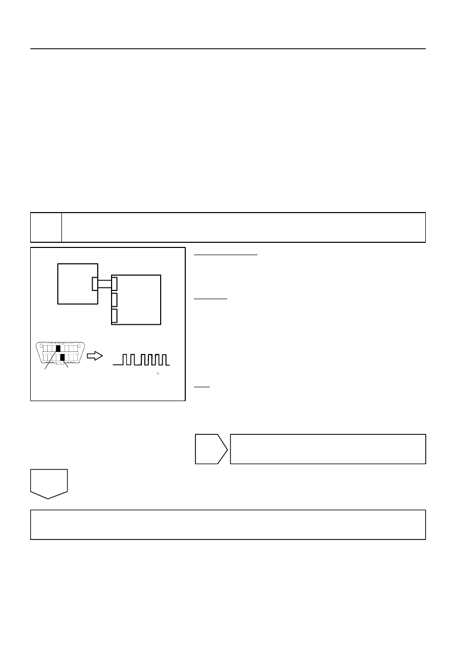
1
Check DTC.
PREPARATION:
(a)
Connect the connectors to the airbag sensor assembly.
(b)
Connect the negative (–) terminal cable to the battery,
and wait for at least 2 seconds.
CHECK:
(a)
Turn the ignition switch to the ON position, and wait for at
least 60 seconds.
(b)
Clear the DTCs stored in memory (see page
(c)
Turn the ignition switch to the LOCK position.
(d)
Turn the ignition switch to the ON position, and wait for at
least 60 seconds.
(e)
OK:
DTC B1635/24 is not output.
HINT:
Codes other than DTC B1635/24 may be output at this time, but
they are not related to this check.
NG
Go to step 2.
OK
From the results of the above inspection, the malfunctioning part can now be considered normal.
To make sure of this, use the simulation method to check (see page
C91384
H01010
G27652
H23575
Curtain Shield
Airbag Sensor
Assembly LH
Floor Wire No. 2
Airbag
Sensor
Assembly
VUCL
ESCL
A
B
C
D
VUCL
ESCL
SST
A19
S26
DI–1200
–
DIAGNOSTICS
SUPPLEMENTAL RESTRAINT SYSTEM
1394
2
Check connection of connectors.
PREPARATION:
(a)
Turn the ignition switch to the LOCK position.
(b)
Disconnect the negative (–) terminal cable from the battery, and wait for at least 90 seconds.
CHECK:
Check that the connectors are properly connected to the airbag sensor assembly and the curtain shield air-
bag sensor assembly LH.
OK:
The connectors are connected securely.
NG
Connect connectors, then go to step 1.
OK
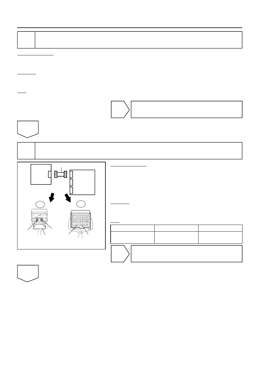
3
Check floor wire No. 2 (open).
PREPARATION:
(a)
Disconnect the connectors from the airbag sensor as-
sembly and the curtain shield airbag sensor assembly LH.
(b)
Using SST, connect S26–2 (VUCL) and S26–1 (ESCL) of
connector ”C”.
SST
09843–18040
CHECK:
Measure the resistance according to the value(s) in the table
below.
OK:
Tester Connection
Condition
Specified Condition
A19–20 (VUCL) –
A19–22 (ESCL)
Always
Below 1
Ω
NG
Repair or replace floor wire No. 2.
OK
C91384
H01010
G27652
H23572
Curtain Shield
Airbag Sensor
Assembly LH
Floor Wire No. 2
Airbag
Sensor
Assembly
VUCL
ESCL
A
B
C
D
A19
C91384
H01010
G27652
H23572
Curtain Shield
Airbag Sensor
Assembly LH
Floor Wire No. 2
Airbag
Sensor
Assembly
VUCL
ESCL
A
B
C
D
A19
–
DIAGNOSTICS
SUPPLEMENTAL RESTRAINT SYSTEM
DI–1201
1395
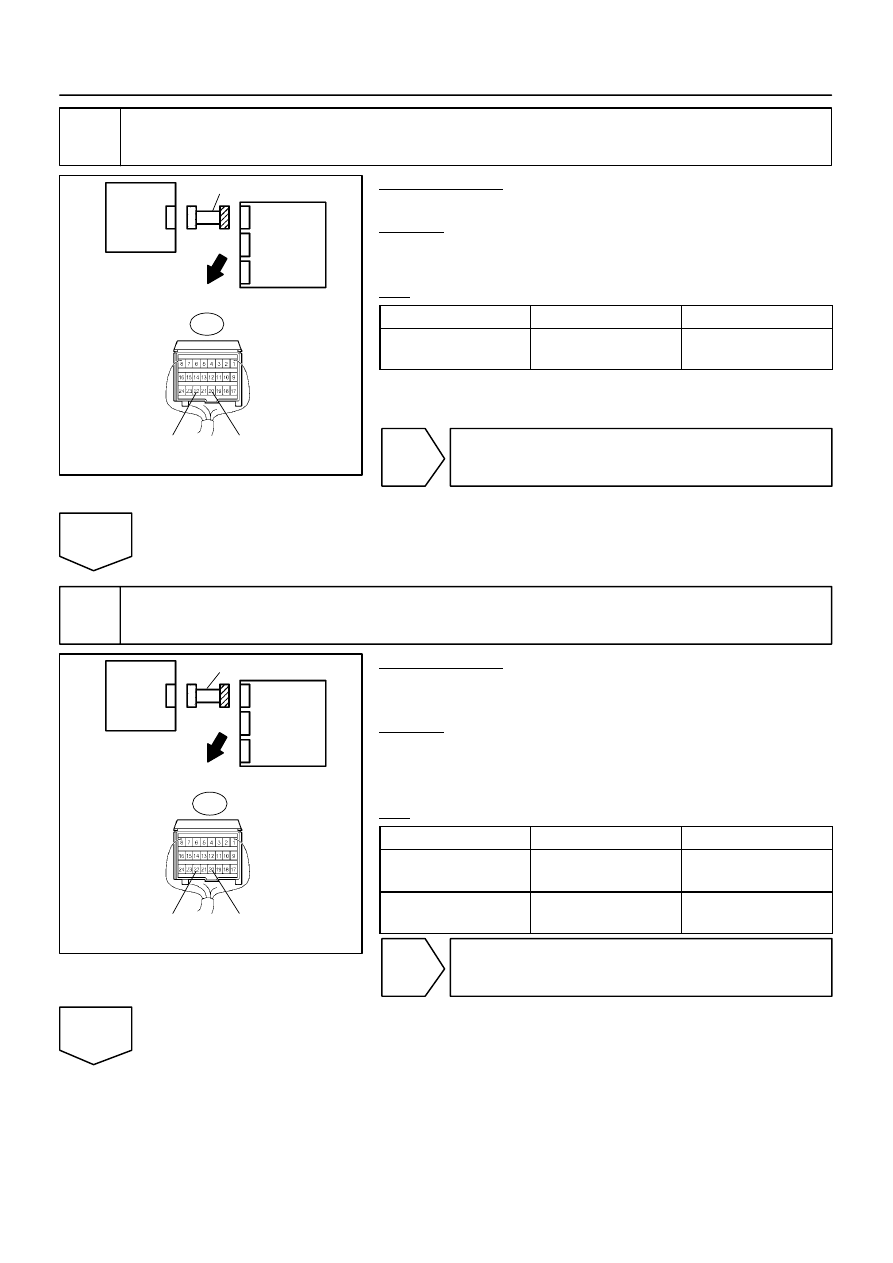
4
Check floor wire No. 2 (short).
PREPARATION:
Disconnect the SST from connector ”C”.
CHECK:
Measure the resistance according to the value(s) in the table
below.
OK:
Tester Connection
Condition
Specified Condition
A19–20 (VUCL) –
A19–22 (ESCL)
Always
1 M
Ω
or higher
NG
Repair or replace floor wire No. 2.
OK
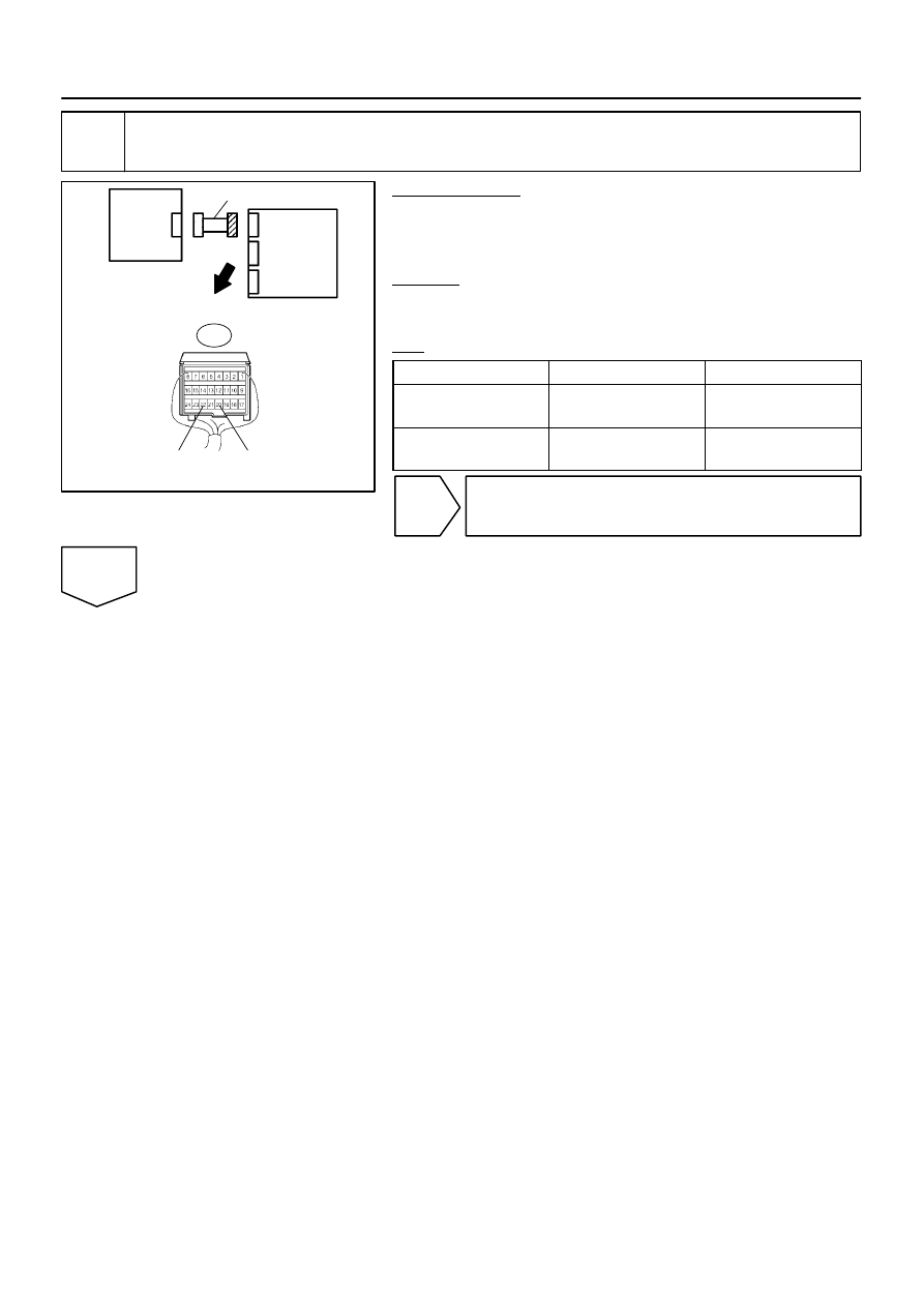
5
Check floor wire No. 2 (short to B+).
PREPARATION:
(a)
Connect the negative (–) terminal cable to the battery,
and wait for at least 2 seconds.
CHECK:
(a)
Turn the ignition switch to the ON position.
(b)
Measure the voltage according to the value(s) in the table
below.
OK:
Tester Connection
Condition
Specified Condition
A19–20 (VUCL) –
Body ground
Ignition switch ON
Below 1 V
A19–22 (ESCL) –
Body ground
Ignition switch ON
Below 1 V
NG
Repair or replace floor wire No. 2.
OK
C91384
H01010
G27652
H23572
Curtain Shield
Airbag Sensor
Assembly LH
Floor Wire No. 2
Airbag
Sensor
Assembly
VUCL
ESCL
A
B
C
D
A19
DI–1202
–
DIAGNOSTICS
SUPPLEMENTAL RESTRAINT SYSTEM
1396
6
Check floor wire No. 2 (short to ground).
PREPARATION:
(a)
Turn the ignition switch to the LOCK position.
(b)
Disconnect the negative (–) terminal cable from the bat-
tery, and wait for at least 90 seconds.
CHECK:
Measure the resistance according to the value(s) in the table
below.
OK:
Tester Connection
Condition
Specified Condition
A19–20 (VUCL) –
Body ground
Always
1 M
Ω
or higher
A19–22 (ESCL) –
Body ground
Always
1 M
Ω
or higher
NG
Repair or replace floor wire No. 2.
OK
Нет комментариевНе стесняйтесь поделиться с нами вашим ценным мнением.
Текст