Toyota Sequoia (2005). Manual — part 372
H43111
H43105
H23817
SVC3
Occupant
Classification
Sensor Rear LH
C
B
D
A
SGD3
O7
SIG3
Occupant
Classification
ECU
Seat Wire No. 1
–
DIAGNOSTICS
SUPPLEMENTAL RESTRAINT SYSTEM
DI–1283
1477
2
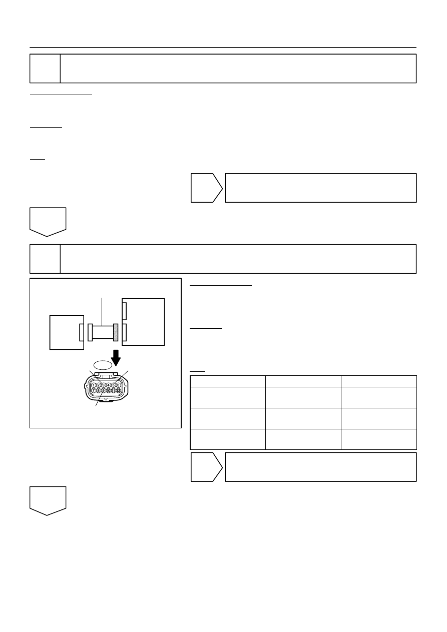
Check connection of connectors.
PREPARATION:
(a)
Turn the ignition switch to the LOCK position.
(b)
Disconnect the negative (–) terminal cable from the battery, and wait for at least 90 seconds.
CHECK:
Check that the connectors are properly connected to the occupant classification ECU and the occupant clas-
sification sensor rear LH.
OK:
The connectors are connected securely.
NG
Connect connectors, then go to step 1.
OK
3
Check seat wire No. 1 (short to B+).
PREPARATION:
(a)
Disconnect the connectors from the occupant classifica-
tion ECU and the occupant classification sensor rear LH.
(b)
Connect the negative (–) terminal cable to the battery.
CHECK:
(a)
Turn the ignition switch to the ON position.
(b)
Measure the voltage according to the value(s) in the table
below.
OK:
Tester Connection
Condition
Specified Condition
O7–3 (SGD3) –
Body ground
Ignition switch ON
Below 1 V
O7–5 (SVC3) –
Body ground
Ignition switch ON
Below 1 V
O7–9 (SIG3) –
Body ground
Ignition switch ON
Below 1 V
NG
Repair or replace seat wire No. 1.
OK
H43111
H43106
H43699
H23818
C
B
D
A
Service
Wire
SVC3
SGD3
SIG3
Occupant
Classification
Sensor Rear LH
Occupant
Classification
ECU
Service Wire
SGD3
SVC3
SIG3
O7
Seat Wire No. 1
O 1
0
DI–1284
–
DIAGNOSTICS
SUPPLEMENTAL RESTRAINT SYSTEM
1478
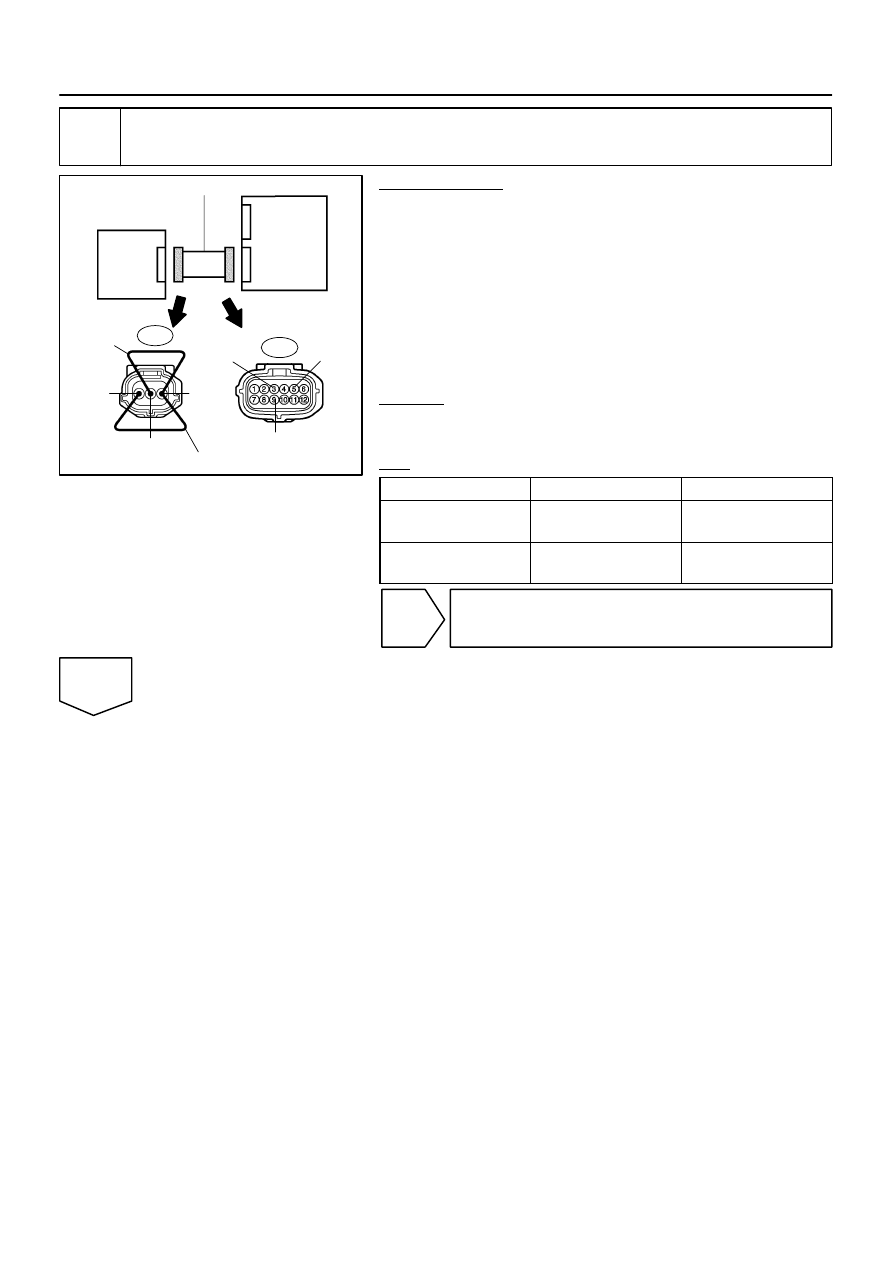
4
Check seat wire No. 1 (open).
PREPARATION:
(a)
Turn the ignition switch to the LOCK position.
(b)
Disconnect the negative (–) terminal cable from the bat-
tery, and wait for at least 90 seconds.
(c)
Using a service wire, connect O10–1 (SVC3) and O10–3
(SGD3), O10–2 (SIG3) and O10–3 (SGD3) of connector
”C”.
NOTICE:
Do not forcibly insert a service wire into the terminals of the
connector when connecting.
CHECK:
Measure the resistance according to the value(s) in the table
below.
OK:
Tester Connection
Condition
Specified Condition
O7–5 (SVC3) –
O7–3 (SGD3)
Always
Below 1
Ω
O7–9 (SIG3) –
O7–3 (SGD3)
Always
Below 1
Ω
NG
Repair or replace seat wire No. 1.
OK
H43111
H43105
H23817
SVC3
Occupant
Classification
Sensor Rear LH
C
B
D
A
SGD3
SIG3
Occupant
Classification
ECU
O7
Seat Wire No. 1
H43111
H43105
H23817
SVC3
Occupant
Classification
Sensor Rear LH
C
B
D
A
SGD3
SIG3
Occupant
Classification
ECU
O7
Seat Wire No. 1
–
DIAGNOSTICS
SUPPLEMENTAL RESTRAINT SYSTEM
DI–1285
1479
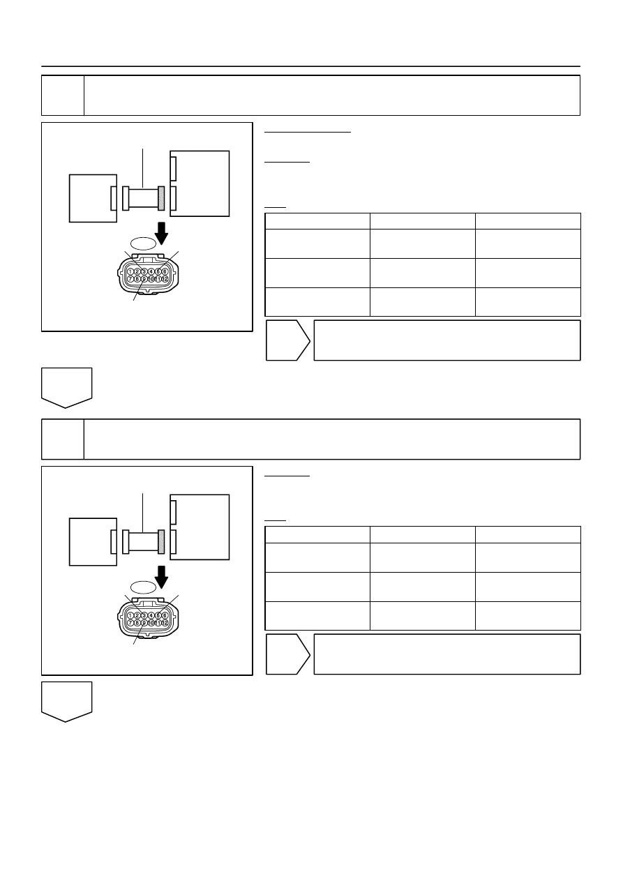
5
Check seat wire No. 1 (short).
PREPARATION:
Disconnect the service wire from connector ”C”.
CHECK:
Measure the resistance according to the value(s) in the table
below.
OK:
Tester Connection
Condition
Specified Condition
O7–9 (SIG3) –
O7–3 (SGD3)
Always
1 M
Ω
or higher
O7–5 (SVC3) –
O7–3 (SGD3)
Always
1 M
Ω
or higher
O7–9 (SIG3) –
O7–5 (SVC3)
Always
1 M
Ω
or higher
NG
Repair or replace seat wire No. 1.
OK
6
Check seat wire No. 1 (short to ground).
CHECK:
Measure the resistance according to the value(s) in the table
below.
OK:
Tester Connection
Condition
Specified Condition
O7–9 (SIG3) –
Body ground
Always
1 M
Ω
or higher
O7–5 (SVC3) –
Body ground
Always
1 M
Ω
or higher
O7–3 (SGD3) –
Body ground
Always
1 M
Ω
or higher
NG
Repair or replace seat wire No. 1.
OK

DI–1286
–
DIAGNOSTICS
SUPPLEMENTAL RESTRAINT SYSTEM
1480
7
Check DTC.
PREPARATION:
(a)
Connect the connectors to the occupant classification ECU and the occupant classification sensor rear
LH.
(b)
Connect the negative (–) terminal cable to the battery.
CHECK:
(a)
Turn the ignition switch to the ON position.
(b)
Clear the DTCs stored in memory (see page
).
HINT:
First clear DTCs stored in the occupant classification ECU and then in the airbag sensor assembly.
(c)
Turn the ignition switch to the LOCK position.
(d)
Turn the ignition switch to the ON position.
(e)
Using the hand–held tester, check the DTCs of the occupant classification ECU (see page
OK:
DTC B1782 is not output.
HINT:
Codes other than DTC B1782 may be output at this time, but they are not related to this check.
NG
OK
From the results of the above inspection, the malfunctioning part can now be considered normal.
To make sure of this, use the simulation method to check (see page
Нет комментариевНе стесняйтесь поделиться с нами вашим ценным мнением.
Текст