Toyota Sequoia (2005). Manual — part 370
H43111
H43105
H23817
SGD2
Occupant
Classification
Sensor Front RH
C
B
D
A
SIG2
SVC2
Occupant
Classification
ECU
Seat Wire No. 1
O7
H43111
H43105
H23817
SGD2
Occupant
Classification
Sensor Front RH
C
B
D
A
SIG2
SVC2
Occupant
Classification
ECU
Seat Wire No. 1
O7
–
DIAGNOSTICS
SUPPLEMENTAL RESTRAINT SYSTEM
DI–1275
1469
5
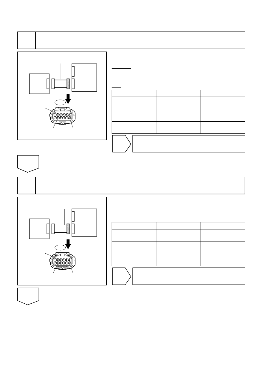
Check seat wire No. 1 (short).
PREPARATION:
Disconnect the service wire from connector ”C”.
CHECK:
Measure the resistance according to the value(s) in the table
below.
OK:
Tester Connection
Condition
Specified Condition
O7–8 (SIG2) –
O7–2 (SGD2)
Always
1 M
Ω
or higher
O7–12 (SVC2) –
O7–2 (SGD2)
Always
1 M
Ω
or higher
O7–8 (SIG2) –
O7–12 (SVC2)
Always
1 M
Ω
or higher
NG
Repair or replace seat wire No. 1.
OK
6
Check seat wire No. 1 (short to ground).
CHECK:
Measure the resistance according to the value(s) in the table
below.
OK:
Tester Connection
Condition
Specified Condition
O7–8 (SIG2) –
Body ground
Always
1 M
Ω
or higher
O7–12 (SVC2) –
Body ground
Always
1 M
Ω
or higher
O7–2 (SGD2) –
Body ground
Always
1 M
Ω
or higher
NG
Repair or replace seat wire No. 1.
OK

DI–1276
–
DIAGNOSTICS
SUPPLEMENTAL RESTRAINT SYSTEM
1470
7
Check DTC.
PREPARATION:
(a)
Connect the connectors to the occupant classification ECU and the occupant classification sensor
front RH.
(b)
Connect the negative (–) terminal cable to the battery.
CHECK:
(a)
Turn the ignition switch to the ON position.
(b)
Clear the DTCs stored in memory (see page
).
HINT:
First clear DTCs stored in the occupant classification ECU and then in the airbag sensor assembly.
(c)
Turn the ignition switch to the LOCK position.
(d)
Turn the ignition switch to the ON position.
(e)
Using the hand–held tester, check the DTCs of the occupant classification ECU (see page
OK:
DTC B1781 is not output.
HINT:
Codes other than DTC B1781 may be output at this time, but they are not related to this check.
NG
OK
From the results of the above inspection, the malfunctioning part can now be considered normal.
To make sure of this, use the simulation method to check (see page

–
DIAGNOSTICS
SUPPLEMENTAL RESTRAINT SYSTEM
DI–1277
1471
8
Replace occupant classification ECU.
(a)
Turn the ignition switch to the LOCK position.
(b)
Disconnect the negative (–) terminal cable from the battery, and wait for at least 90 seconds.
(c)
Replace the occupant classification ECU (see page
HINT:
Perform the inspection using parts from a normal vehicle if possible.
NEXT
9
Perform zero point calibration.
(a)
Connect the negative (–) terminal cable to the battery.
(b)
Connect the hand–held tester to the DLC3.
(c)
Turn the ignition switch to the ON position.
(d)
Using the hand–held tester, perform ”Zero point calibration” (see page
).
OK:
The ”COMPLETED” is displayed.
NG
OK
10
Perform sensitivity check.
Using the hand–held tester, perform ”Sensitivity check” (see page
OK:
Standard value: 27 to 33 kg (59.52 to 72.75 lb)
NG
OK

DI–1278
–
DIAGNOSTICS
SUPPLEMENTAL RESTRAINT SYSTEM
1472
11
Check DTC.
CHECK:
(a)
Turn the ignition switch to the ON position.
(b)
Clear the DTCs stored in memory (see page
).
HINT:
First clear DTCs stored in the occupant classification ECU and then in the airbag sensor assembly.
(c)
Turn the ignition switch to the LOCK position.
(d)
Turn the ignition switch to the ON position.
(e)
Using the hand–held tester, check the DTCs of the occupant classification ECU (see page
OK:
DTC B1781 is not output.
HINT:
Codes other than DTC B1781 may be output at this time, but they are not related to this check.
NG
OK
END
Нет комментариевНе стесняйтесь поделиться с нами вашим ценным мнением.
Текст