Toyota Sequoia (2005). Manual — part 451
I24837
IG
Transponder Key ECU
D
3
T16
O
J43
J/C
W–L
8
OP3
D6
DLC3
CG
4
A
A
O
–
DIAGNOSTICS
ENGINE IMMOBILISER SYSTEM
DI–1599
1793
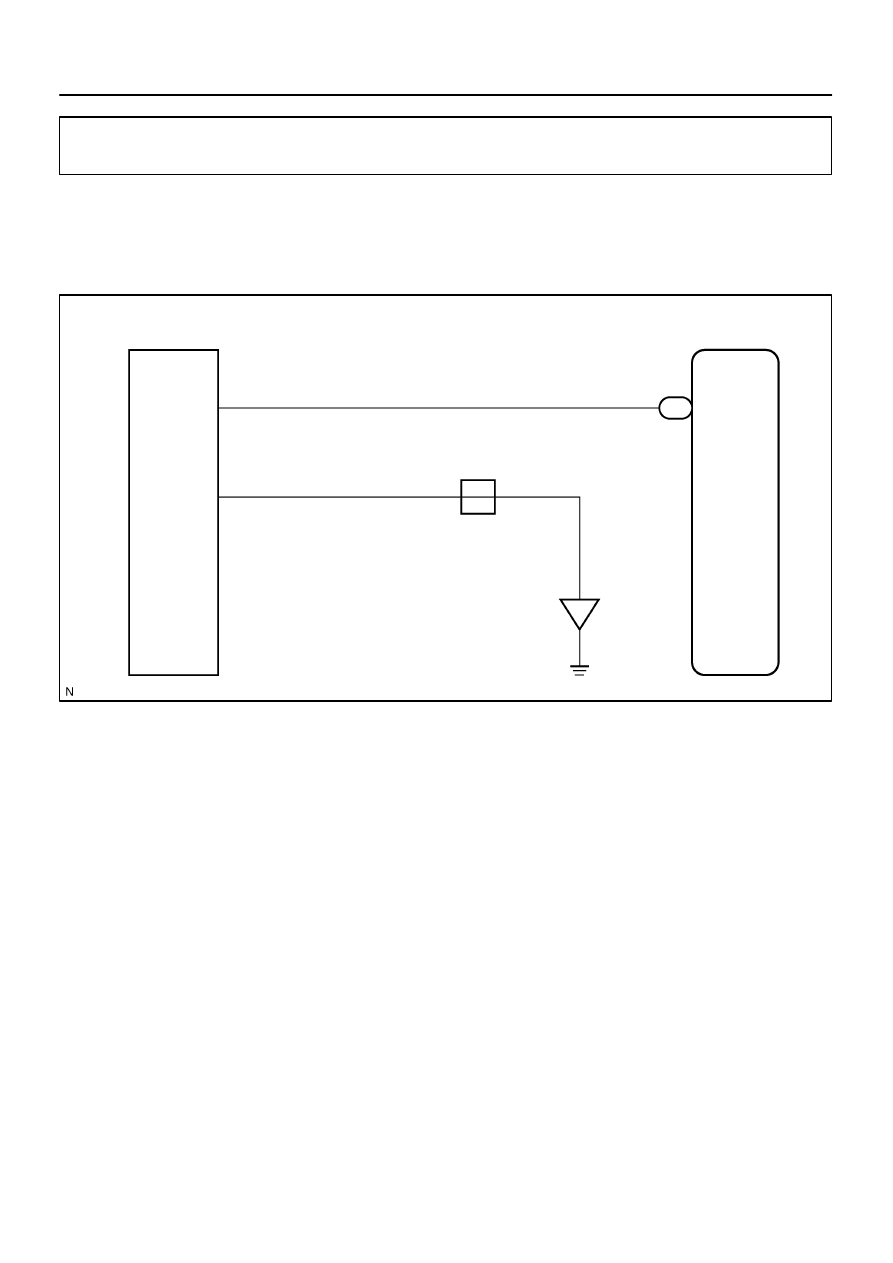
Diagnosis Circuit
CIRCUIT DESCRIPTION
This circuit sends a signal to the ECU that outputs DTCs.
WIRING DIAGRAM
DIABK–03
A04550
CG
OP3
1 2 3 4 5 6 7 8
9 1011
13 1516
12 14
DI–1600
–
DIAGNOSTICS
ENGINE IMMOBILISER SYSTEM
1794
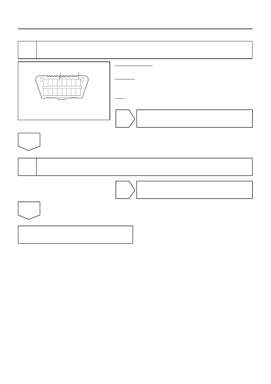
INSPECTION PROCEDURE
1
Check voltage between terminals OP3 and CG
of DLC3.
PREPARATION:
Turn the ignition switch ON.
CHECK:
Measure the voltage between terminals OP3 and CG of the
DLC3.
OK:
Voltage: 10 to 14 V
OK
Proceed to next circuit inspection shown in
problem symptoms table (See page
NG
2
Check harness and connector between transponder key ECU and DLC3, DLC3
and body ground (See page
NG
Repair or replace harness or connector.
OK
Replace transponder key ECU
(See page
).
DID8N–01
–
DIAGNOSTICS
COMBINATION METER SYSTEM
DI–1601
1795
COMBINATION METER SYSTEM
PRECAUTION
NOTICE:
When disconnecting the battery terminal, initialize the following system after the terminal is recon-
nected.
System Name
See Page
Back Door Power Window Control System
DID8O–01
I28426
Fuel Tank
Fuel Sender Gauge
DI–1602
–
DIAGNOSTICS
COMBINATION METER SYSTEM
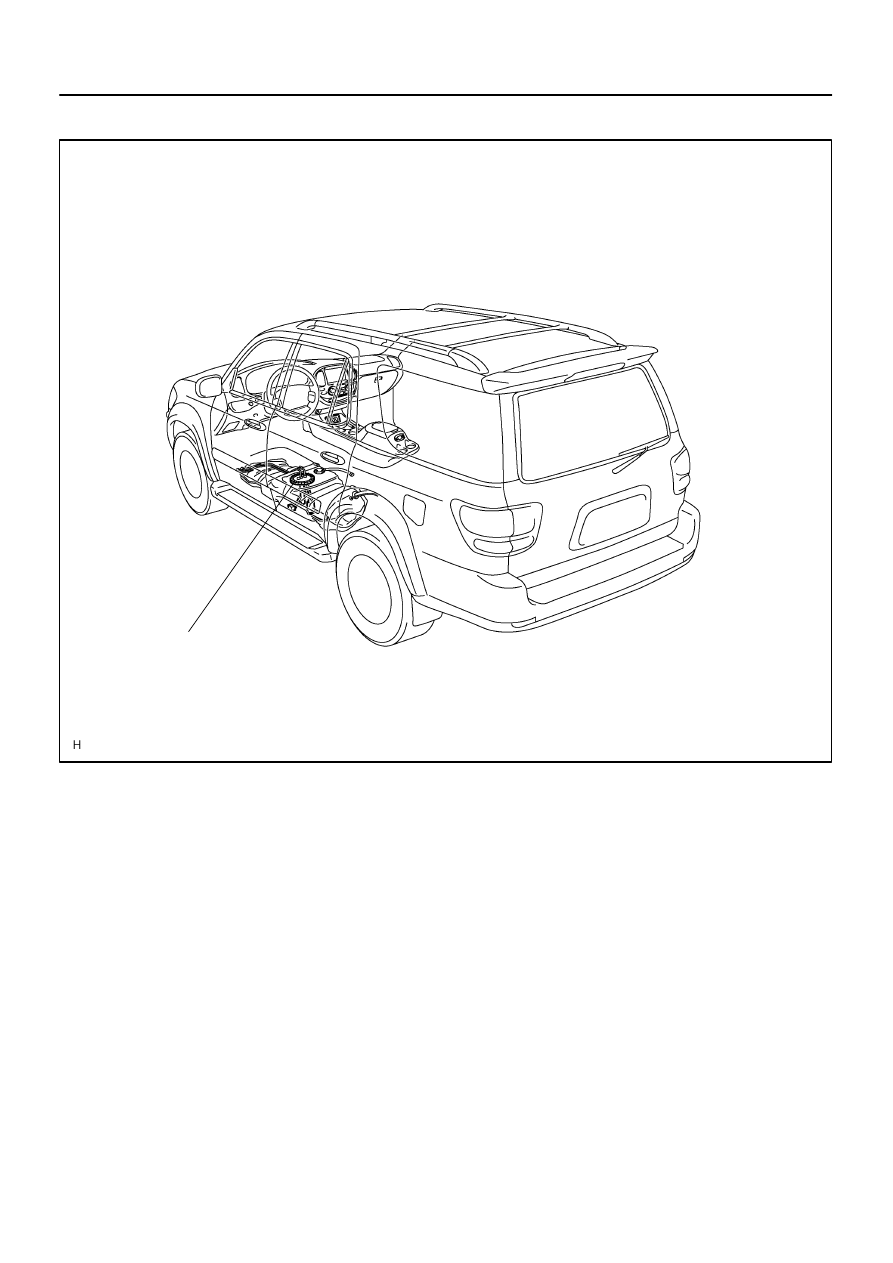
1796
LOCATION
Нет комментариевНе стесняйтесь поделиться с нами вашим ценным мнением.
Текст