Toyota Sequoia (2005). Manual — part 450
I24831
Transponder Key ECU
Sub J/B No. 3
+B
J43
J/C
5
1
O
Battery
F10
FL Block
W–R
B
4
IG
B
Engine Room J/B
W–R
3
2
1J
1E
Instrument Panel J/B
A
A
GND
O
14
T16
T16
1
2
W–R
3A
3B
8
1
2C
2D
ECU–B
SHORT PIN
–
DIAGNOSTICS
ENGINE IMMOBILISER SYSTEM
DI–1595
1789
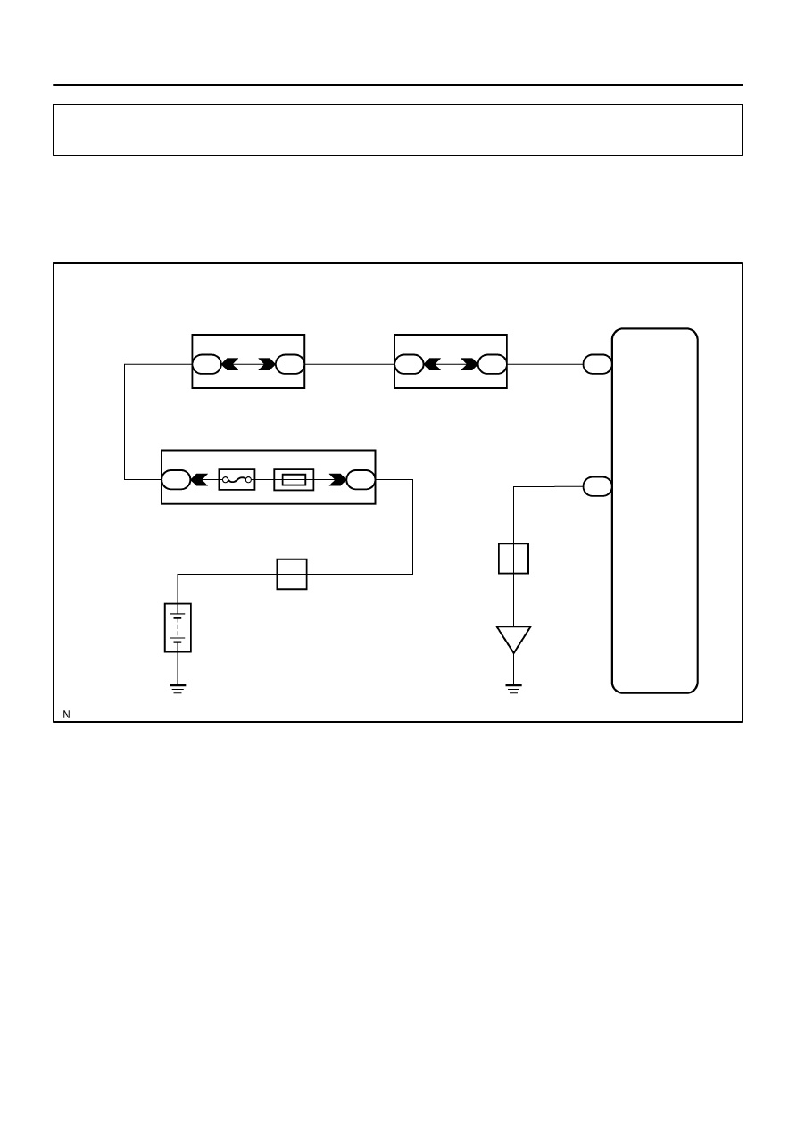
Power source circuit
CIRCUIT DESCRIPTION
This circuit provides power to operate the transponder key ECU.
WIRING DIAGRAM
DI7TO–07
DI–1596
–
DIAGNOSTICS
ENGINE IMMOBILISER SYSTEM
1790
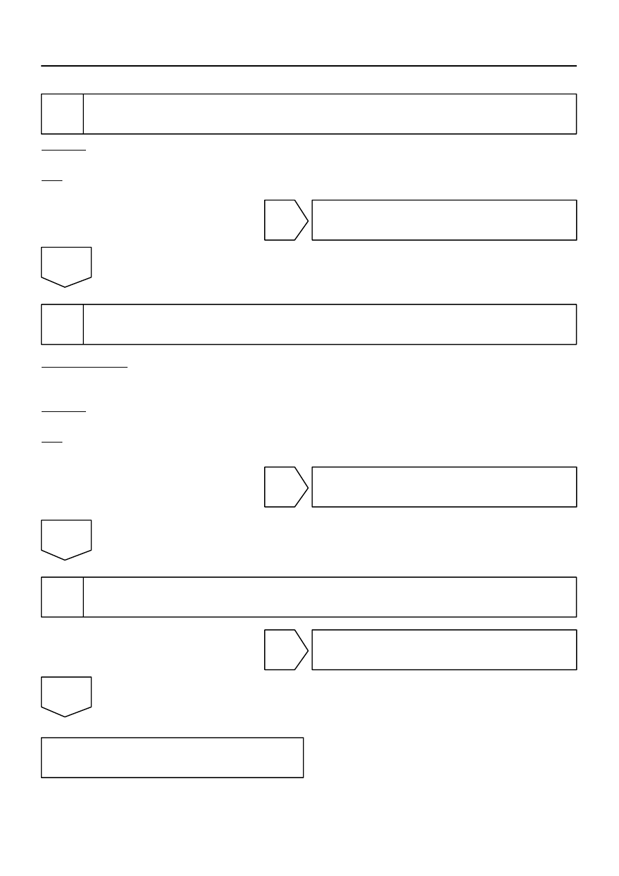
INSPECTION PROCEDURE
1
Check ECU–B fuse.
CHECK:
Check for continuity of the ECU–B fuse.
OK:
Continuity
NG
Replace fuse.
OK
2
Check voltage between terminals +B and GND of transponder key ECU connec-
tor.
PREPARATION:
(a)
Turn the ignition switch OFF.
(b)
Disconnect the transponder key ECU connector.
CHECK:
Measure the voltage between terminals +B and GND.
OK:
Voltage: 10 to 14 V
OK
Proceed to next circuit inspection shown in
problem symptoms table (See page
NG
3
Check wire harness and connector between terminal GND of transponder key
ECU and body ground (See page
).
NG
Repair or replace wire harness or connector.
OK
Check and repair wire harness and connec-
tor between transponder key ECU and bat-
tery.
I24835
Instrument Panel J/B
6
9
BR
1F
1D
W–B
A
IE
J8
J/C
12
C6
C5
16
LG–B
7
T16 IND
Combination Meter
Transponder Key ECU
Security
–
DIAGNOSTICS
ENGINE IMMOBILISER SYSTEM
DI–1597
1791
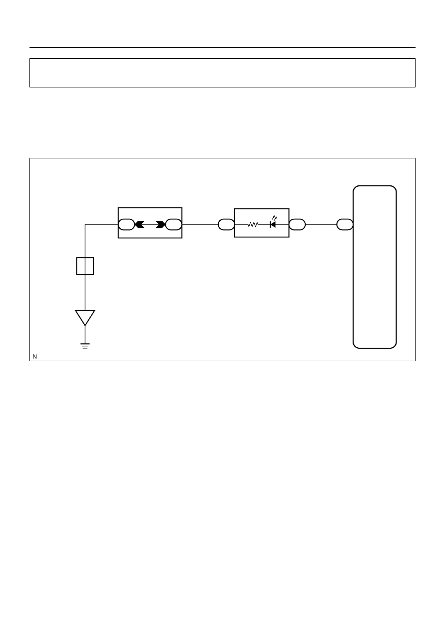
Security Indicator Light Circuit
CIRCUIT DESCRIPTION
When the transponder key is registered, the transponder key ECU outputs the key registration condition by
illuminating, blinking or turning off the security indicator.
WIRING DIAGRAM
DIABJ–03
I24836
ON
IND
(–)
(+)
DI–1598
–
DIAGNOSTICS
ENGINE IMMOBILISER SYSTEM
1792
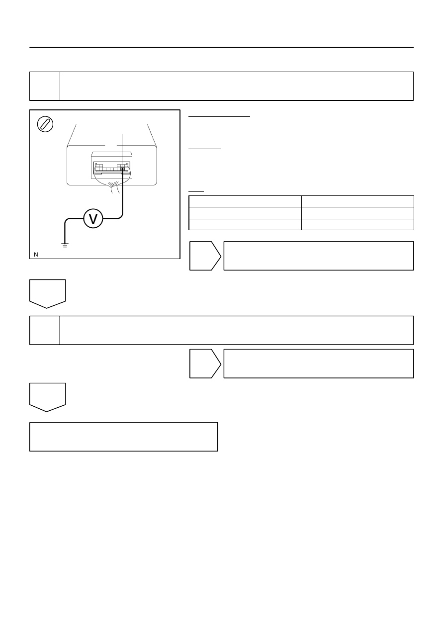
INSPECTION PROCEDURE
1
Check voltage between terminal IND of transponder key ECU connector and
body ground.
PREPARATION:
Turn the ignition switch to the ON position and enter diagnosis
mode.
CHECK:
Measure the voltage between terminal IND of the transponder
key ECU connector and body ground when the security indica-
tor light is on and when it is off.
OK:
Indicator light
Voltage
ON
3 to 6 V
OFF
Below 1 V
NG
Proceed to next circuit inspection shown in
problem symptoms table (See page
OK
2
Check combination meter (See page
NG
Replace combination meter.
OK
Check and replace wire harness and connec-
tor (See page
Нет комментариевНе стесняйтесь поделиться с нами вашим ценным мнением.
Текст