Toyota Sequoia (2005). Manual — part 856
–
BODY ELECTRICAL
TROUBLESHOOTING
BE–9
3413
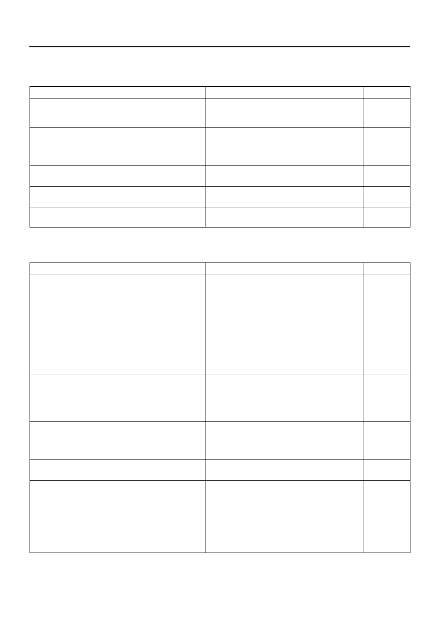
POWER DOOR LOCK CONTROL SYSTEM
This system uses the multiplex communication system, so check diagnosis system of the multiplex commu-
nication system before you proceed with troubleshooting.
Symptom
Suspect Area
See page
All the doors cannot be locked or unlocked.
(Power window control system is normal.)
1. Door Unlock Detection Switch
2. Door Key Lock and Unlock Switch
3. Driver Door ECU
–
Only one back lock control does not operate.
1. Back Door Lock Motor
2. Back Door Unlock Detection Switch
3. Back Door Key Lock and Unlock Switch
4. Back Door ECU
–
Driver door key related function does not operate.
1. Door Key Lock and Unlock Switch
2. Driver Door ECU
–
Front passenger door key related function does not operate.
1. Door Key Lock and Unlock Switch
2. Passenger Door ECU
–
Back door key related function does not operate.
1. Door Key Lock and Unlock Switch
2. Back Door ECU
–
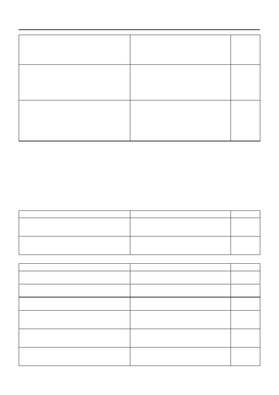
THEFT DETERRENT SYSTEM
This system uses the multiplex communication system, so check diagnosis system of the multiplex commu-
nication system before you proceed with troubleshooting.
Symptom
Suspect Area
See page
The theft deterrent system cannot be set.
1. Key Unlock Warning Switch Circuit
2. Door Unlock Detection Switch Circuit (Driver Door ECU)
Door Unlock Detection Switch Circuit (Passenger Door
ECU)
Door Unlock Detection Switch Circuit (Back Door ECU)
Door Unlock Detection Switch Circuit (Body ECU)
3. Engine Hood Courtesy Switch Circuit
4. Back Door Courtesy Light Switch
5. Courtesy Light Switch Circuit
6. Glass Breakage Sensor Circuit (*1)
7. Body ECU
–
The system cannot be canceled when the ignition switch is turned
ON with a key.
1. AM1 Fuse
2. AM2 Fuse
3. Key Unlock Warning Switch Circuit
4. Ignition Switch
5. Body ECU
–
The system cannot be canceled when the back door is unlocked
with a key.
1. Back Door Unlock Detection Switch Circuit
2. Back Door Key Lock and Unlock Switch Circuit
3. Back door ECU
4. Body ECU
–
–
The system does not operate when the engine hood is opened.
1. Engine Hood Courtesy Switch Circuit
2. Body ECU
–
Some of the system does not operate.
(Headlight does not come on.)
1. Bulb
2. HEAD Relay
3. DIMMER Relay
4. DRL No. 4 Relay
5. Headlight Dimmer Switch
6. Light Control Switch
7. Wire Harness
8. Body ECU
–
–
–
BE–10
–
BODY ELECTRICAL
TROUBLESHOOTING
3414
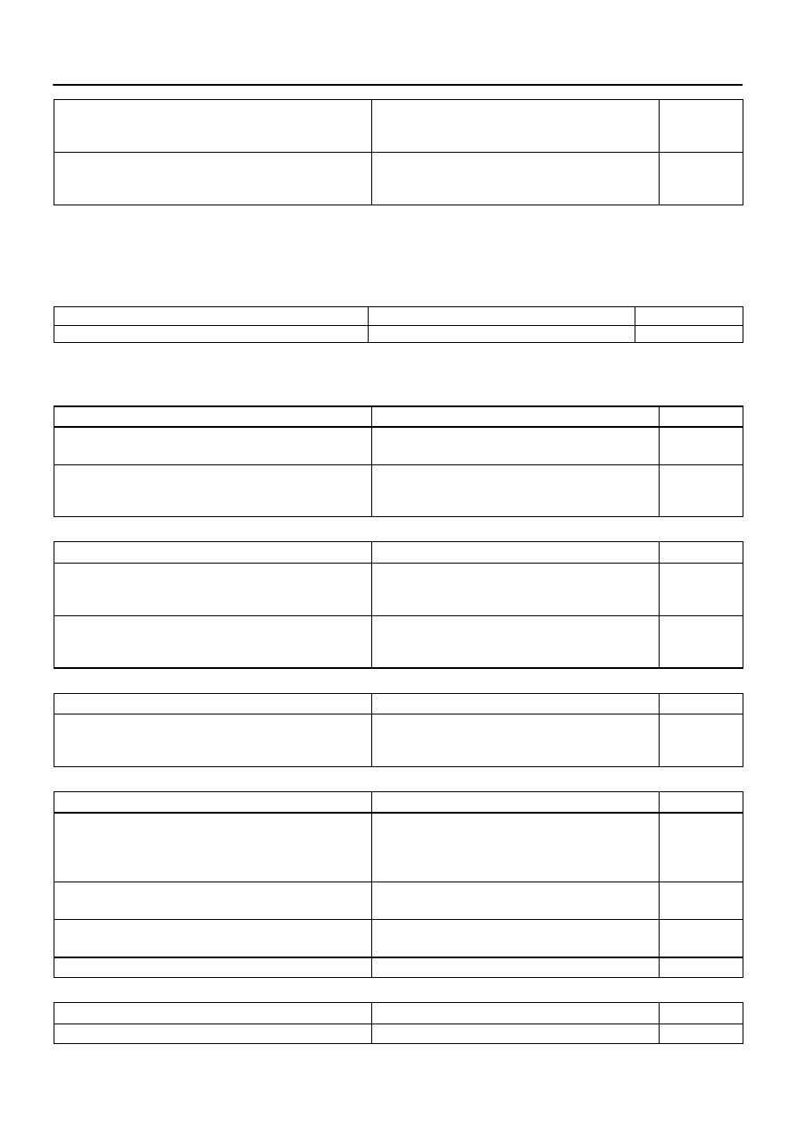
Some of the system does not operate.
(Taillight does not come on.)
1. TAIL Fuse
2. TAILLIGHT Relay
3. Light Control Switch
4. Wire Harness
5. Body ECU
–
–
Some of the system do not operate.
(Theft deterrent horn or vehicle horn does not sound.)
1. HORN Fuse
2. SECURITY HORN Fuse
3. HORN Relay Circuit
4. Theft Deterrent Horn Circuit
5. Horn
6. Body ECU
–
While the warning is given, the system cannot be canceled by
unlocking the door with a key or transmitter.
1. Door Key Lock and Unlock Switch Circuit (Driver Door
ECU)
Door Key Lock and Unlock Switch Circuit (Passenger
Door ECU)
Door Key Lock and Unlock Switch Circuit (Back Door
ECU)
2. Body ECU
–
*1: w/ Glass breakage sensor
WIRELESS DOOR LOCK CONTROL SYSTEM
This system uses the multiplex communication system, so check diagnosis system of the multiplex commu-
nication system before you proceed with troubleshooting.
HINT:
Troubleshooting of the wireless door lock control system is based on the premise that the door lock
control system operates normally. Accordingly, before troubleshooting the wireless door lock control
system, first make certain that the door lock control system operates normally.
If the trouble still reappears even though there are no abnormalities in any of the other circuits, check
and replace the Wireless Door Lock Control Receiver as the last step.
Symptom
Suspect Area
See page
All functions of wireless door lock control system do not operate.
1. Transmitter
2. Wireless Door Lock Control Receiver Circuit
3. Body ECU
–
Wireless door lock operates, but the buzzer does not sound.
(The buzzer does not sound when the customize function prohib-
its.)
1. Wireless Door Lock Buzzer Circuit
2. Body ECU
–
POWER SEAT CONTROL SYSTEM (w/o Driving Position Memory)
Symptom
Suspect Area
See page
Both Driver and Passenger Power seats do not operate.
1. PWR SEAT Fuse
2. Wire Harness
–
Driver’s seat does not operate.
1. Power Seat Switch (D)
2. Wire Harness
–
Passenger’s seat does not operate.
1. Power Seat Switch (P)
2. Wire Harness
–
”Slide operation” does not operate.
1. Power Seat Switch (D, P)
2. Slide Motor (D, P)
3. Wire Harness
–
”Front Vertical Operation” does not operate.
1. Power Seat Switch (D)
2. Front Vertical Motor (D)
3. Wire Harness
–
”Lifter Operation” does not operate.
1. Power Seat Switch (D)
2. Lifter Motor (D)
3. Wire Harness
–
–
BODY ELECTRICAL
TROUBLESHOOTING
BE–11
3415
”Reclining Operation” does not operate.
1. Power Seat Switch (D, P)
2. Reclining Motor (D, P)
3. Wire Harness
–
”Lumbar Support Operation” does not operate.
1. Power Seat Switch (D)
2. Lumbar Support Motor (D)
3. Wire Harness
–
(D): Driver’s Seat
(P): Passenger’s Seat
POWER SEAT CONTROL SYSTEM (w/ Driving Position Memory)
This system uses the multiplex communication system, so check diagnosis system of the multiplex commu-
nication system before you proceed with troubleshooting.
Symptom
Suspected Area
See Page
Power seat control system abnormal operation.
See DIAGNOSIS SYSTEM
POWER MIRROR CONTROL SYSTEM (w/o Driving Position Memory)
This system uses the multiplex communication system, so check diagnosis system of the multiplex commu-
nication system before you proceed with troubleshooting.
Symptom
Suspect Area
See page
Mirror does not operate.
1. Mirror Switch
2. Wire Harness
–
Mirror operates abnormally.
1. Mirror Switch
2. Mirror Motor
3. Wire Harness
–
POWER MIRROR CONTROL SYSTEM (w/ Driving Position Memory)
Symptom
Suspect Area
See page
Remote control mirror LH only does not operate.
(w/ Driving position memory)
1. Remote control mirror motor LH circuit
2. Remote control mirror position sensor LH circuit
3. Driver door ECU
–
Remote control mirror RH only does not operate.
(w/ Driving position memory)
1. Remote control mirror motor RH circuit
2. Remote control mirror position sensor RH circuit
3. Passenger door ECU
–
ELECTRO CHROMIC MIRROR SYSTEM
Symptom
Suspect Area
See page
Electro Chromic Inner Mirror does not operate.
1. ECU–IG Fuse
2. Electro Chromic Inner Mirror
3. Wire Harness
–
SEAT HEATER SYSTEM
Symptom
Suspect Area
See page
Seat heaters do not operate.
(Driver’s and Passenger’s)
1. SEAT HTR Fuse
2. Seat Heater Switch (D, P)
3. Seat Heater
4. Wire Harness
–
Driver’s seat heater does not operate.
1. Seat Heater Switch (D, P)
2. Wire Harness
–
Passenger’s seat heater does not operate.
1. Seat Heater Switch (D, P)
2. Wire Harness
–
Seat heater temperature is too hot.
Seat Heater
AUDIO SYSTEM
Symptom
Suspect Area
See page
Audio system abnormal operation.
See DIAGNOSIS SYSTEM
BE–12
–
BODY ELECTRICAL
TROUBLESHOOTING
3416
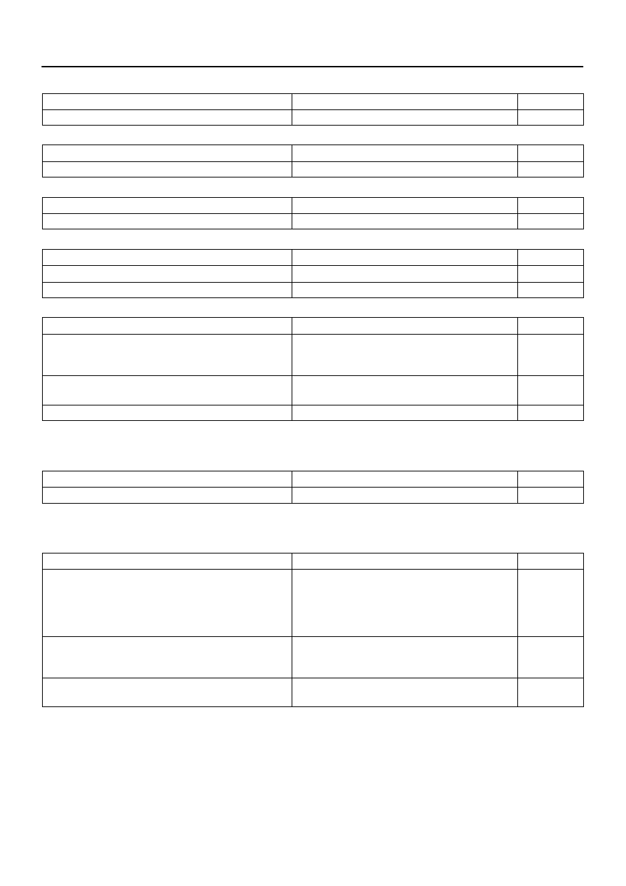
NAVIGATION SYSTEM
Symptom
Suspect Area
See page
Navigation system abnormal operation.
See DIAGNOSIS SYSTEM
REAR SEAT ENTERTAINMENT SYSTEM
Symptom
Suspect Area
See page
Rear seat entertainment system abnormal operation.
See DIAGNOSIS SYSTEM
REAR SEAT AUDIO SYSTEM
Symptom
Suspect Area
See page
Rear seat audio system abnormal operation.
See DIAGNOSIS SYSTEM
CLOCK SYSTEM
Symptom
Suspect Area
See page
Clock does not operate.
TROUBLESHOOTING NO.1
Clock loses or gains time.
TROUBLESHOOTING NO.2
GARAGE DOOR OPENER SYSTEM
Symptom
Suspect Area
See page
The equipment of which code has been registered does not oper-
ate.
1. Garage Door Opener Switch
2. Wire Harness
3. *
–
–
LED does not come on. (Even though either switch is pressed.)
1. Garage Door Opener Switch
2. Wire Harness
–
LED does not come on. (Only one switch is pressed.)
Garage Door Opener Switch
* As the GARAGE DOOR OPENER on the vehicle side seems to be normal, check the OPENER on the
equipment side, of which code has been registered.
ENGINE IMMOBILISER SYSTEM
Symptom
Suspect Area
See page
Engine immobilizer system does not operate.
See DIAGNOSIS SYSTEM
HORN SYSTEM
This system uses the multiplex communication system, so check diagnosis system of the multiplex commu-
nication system before you proceed with troubleshooting.
Symptom
Suspect Area
See page
Horn system does not operate.
1. HORN Fuse
2. HORN Relay Circuit
3. Horn Switch Circuit
4. Horn
5. Body ECU
–
Horn blow all the time.
1. HORN Relay Circuit
2. Horn Switch Circuit
3. Body ECU
–
One horn operates but the other horn does not operate.
1. Horn
2. Wire Harness
–
Нет комментариевНе стесняйтесь поделиться с нами вашим ценным мнением.
Текст