Toyota Sequoia (2005). Manual — part 369
H24040
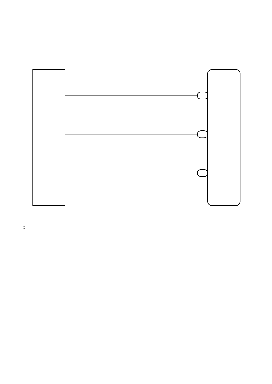
Occupant
Classification ECU
O7
2
SGD2
O9
Occupant Classification
Sensor Front RH
O7
8
SIG2
O7
12
SVC2
SGD2
SIG2
SVC2
3
2
1
B–Y
LG
P
–
DIAGNOSTICS
SUPPLEMENTAL RESTRAINT SYSTEM
DI–1271
1465
WIRING DIAGRAM
DI–1272
–
DIAGNOSTICS
SUPPLEMENTAL RESTRAINT SYSTEM
1466
INSPECTION PROCEDURE
HINT:
If troubleshooting (wire harness inspection) is difficult to perform, remove the passenger seat installa-
tion bolts to see the under surface of seat cushion.
In the above case, hold the seat so that it does not fall down. Holding the seat for a long period of time
may cause a problem, such as seat rail deformation. Hold the seat only as necessary.
1
Check DTC.
CHECK:
(a)
Turn the ignition switch to the ON position.
(b)
Clear the DTCs stored in memory (see page
).
HINT:
First clear DTCs stored in the occupant classification ECU and then in the airbag sensor assembly.
(c)
Turn the ignition switch to the LOCK position.
(d)
Turn the ignition switch to the ON position.
(e)
Using the hand–held tester, check the DTCs of the occupant classification ECU (see page
OK:
DTC B1781 is not output.
HINT:
Codes other than DTC B1781 may be output at this time, but they are not related to this check.
NG
OK
From the results of the above inspection, the malfunctioning part can now be considered normal.
To make sure of this, use the simulation method to check (see page
H43111
H43105
H23817
SGD2
Occupant
Classification
Sensor Front RH
Seat Wire No. 1
C
B
D
A
SIG2
O7
SVC2
Occupant
Classification
ECU
–
DIAGNOSTICS
SUPPLEMENTAL RESTRAINT SYSTEM
DI–1273
1467
2
Check connection of connectors.
PREPARATION:
(a)
Turn the ignition switch to the LOCK position.
(b)
Disconnect the negative (–) terminal cable from the battery, and wait for at least 90 seconds.
CHECK:
Check that the connectors are properly connected to the occupant classification ECU and the occupant clas-
sification sensor front RH.
OK:
The connectors are connected securely.
NG
Connect connectors, then go to step 1.
OK
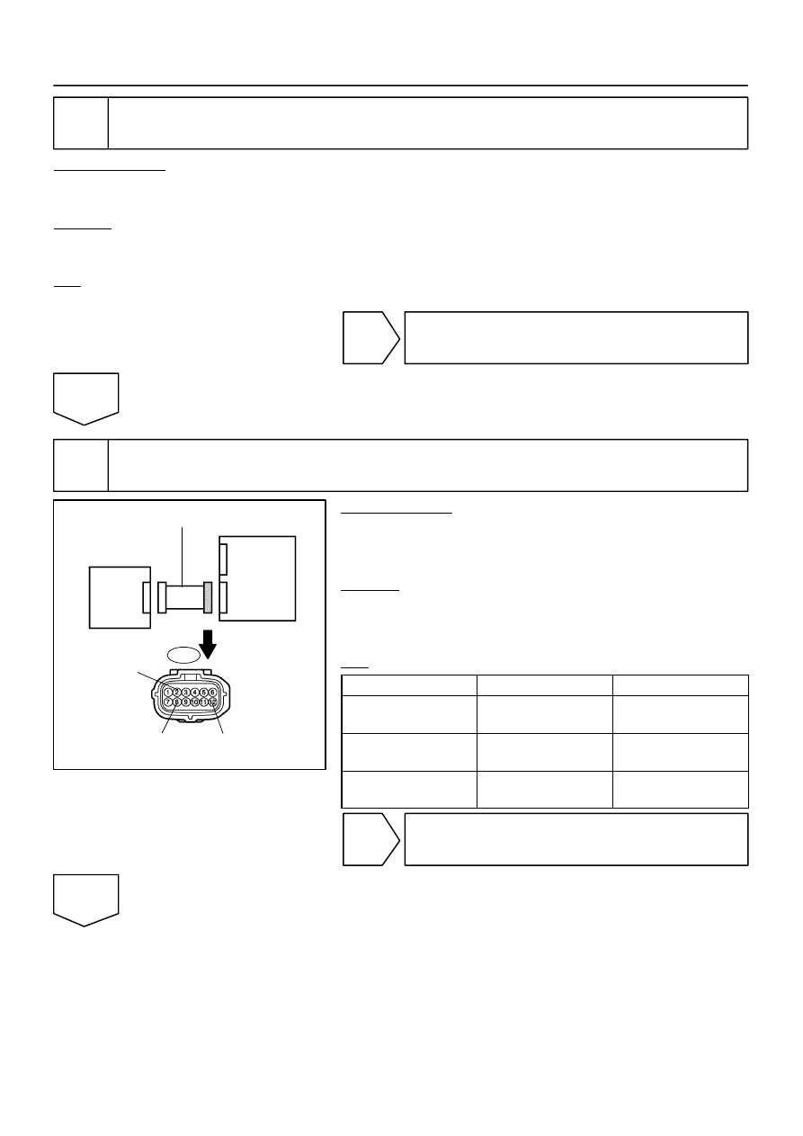
3
Check seat wire No. 1 (short to B+).
PREPARATION:
(a)
Disconnect the connectors from the occupant classifica-
tion ECU and the occupant classification sensor front RH.
(b)
Connect the negative (–) terminal cable to the battery.
CHECK:
(a)
Turn the ignition switch to the ON position.
(b)
Measure the voltage according to the value(s) in the table
below.
OK:
Tester Connection
Condition
Specified Condition
O7–2 (SGD2) –
Body ground
Ignition switch ON
Below 1 V
O7–8 (SIG2) –
Body ground
Ignition switch ON
Below 1 V
O7–12 (SVC2) –
Body ground
Ignition switch ON
Below 1 V
NG
Repair or replace seat wire No. 1.
OK
H43111
H43106
H43699
H23818
C
B
D
A
Occupant
Classification
Sensor Front RH
Occupant
Classification
ECU
SGD2
SIG2
SVC2
Service Wire
Service Wire
SGD2
SIG2
SVC2
Seat Wire No. 1
O7
O9
DI–1274
–
DIAGNOSTICS
SUPPLEMENTAL RESTRAINT SYSTEM
1468
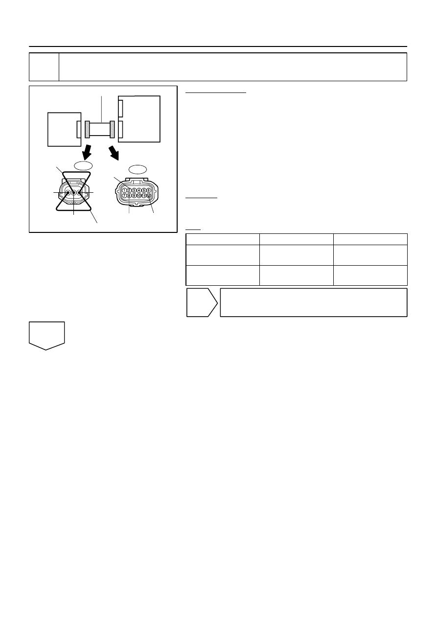
4
Check seat wire No. 1 (open).
PREPARATION:
(a)
Turn the ignition switch to the LOCK position.
(b)
Disconnect the negative (–) terminal cable from the bat-
tery, and wait for at least 90 seconds.
(c)
Using a service wire, connect O9–1 (SVC2) and O9–3
(SGD2), O9–2 (SIG2) and O9–3 (SGD2) of connector
”C”.
NOTICE:
Do not forcibly insert a service wire into the terminals of the
connector when connecting.
CHECK:
Measure the resistance according to the value(s) in the table
below.
OK:
Tester Connection
Condition
Specified Condition
O7–12 (SVC2) –
O7–2 (SGD2)
Always
Below 1
Ω
O7–8 (SIG2) –
O7–2 (SGD2)
Always
Below 1
Ω
NG
Repair or replace seat wire No. 1.
OK
Нет комментариевНе стесняйтесь поделиться с нами вашим ценным мнением.
Текст