Toyota Sequoia (2005). Manual — part 771
R12863
SST
R13282
Matchmarks
Matchmarks
–
SUSPENSION AND AXLE
FRONT LOWER SUSPENSION ARM
SA–77
3073
6.
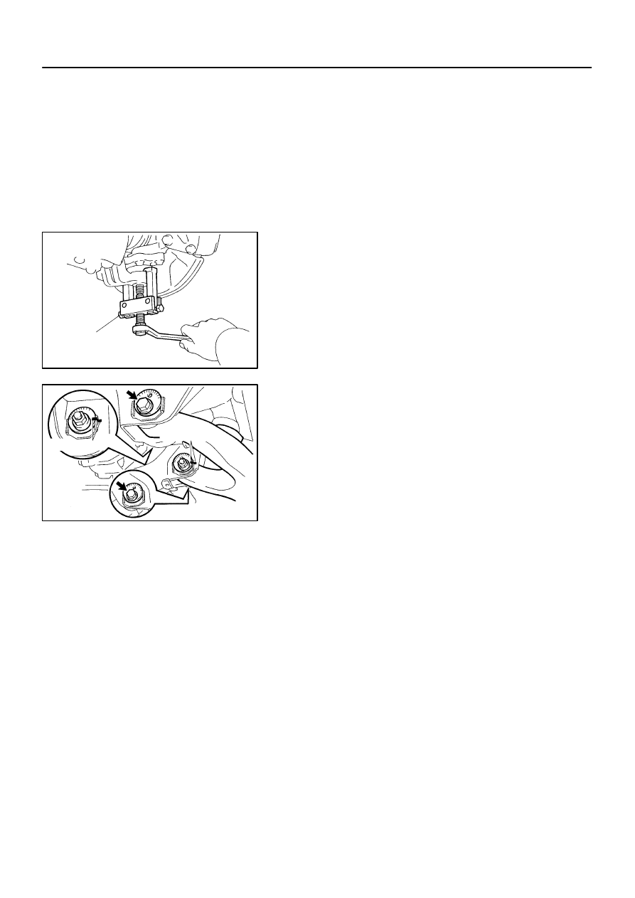
DISCONNECT LOWER BALL JOINT FROM LOWER
SUSPENSION ARM
(a)
Remove the cotter pin and nut.
(b)
Using SST, disconnect the lower ball joint from the lower
suspension arm.
SST
09628–62011
7.
REMOVE LOWER SUSPENSION ARM
(a)
Place matchmarks on the front and rear cam plates and
chassis frame.
(b)
Remove the 2 cam plates, bolts, cams and lower suspen-
sion arm while slightly shifting the power steering gear
rearward.
NOTICE:
Do not damage the power steering gear tubes.
SA24S–02
W01884
SST
SST
F07275
Mark
Mark
Steel Plate
F07276
Marks
Steel Plate
F07277
Removal:
Installation:
SA–78
–
SUSPENSION AND AXLE
FRONT LOWER SUSPENSION ARM
3074
REPLACEMENT
1.
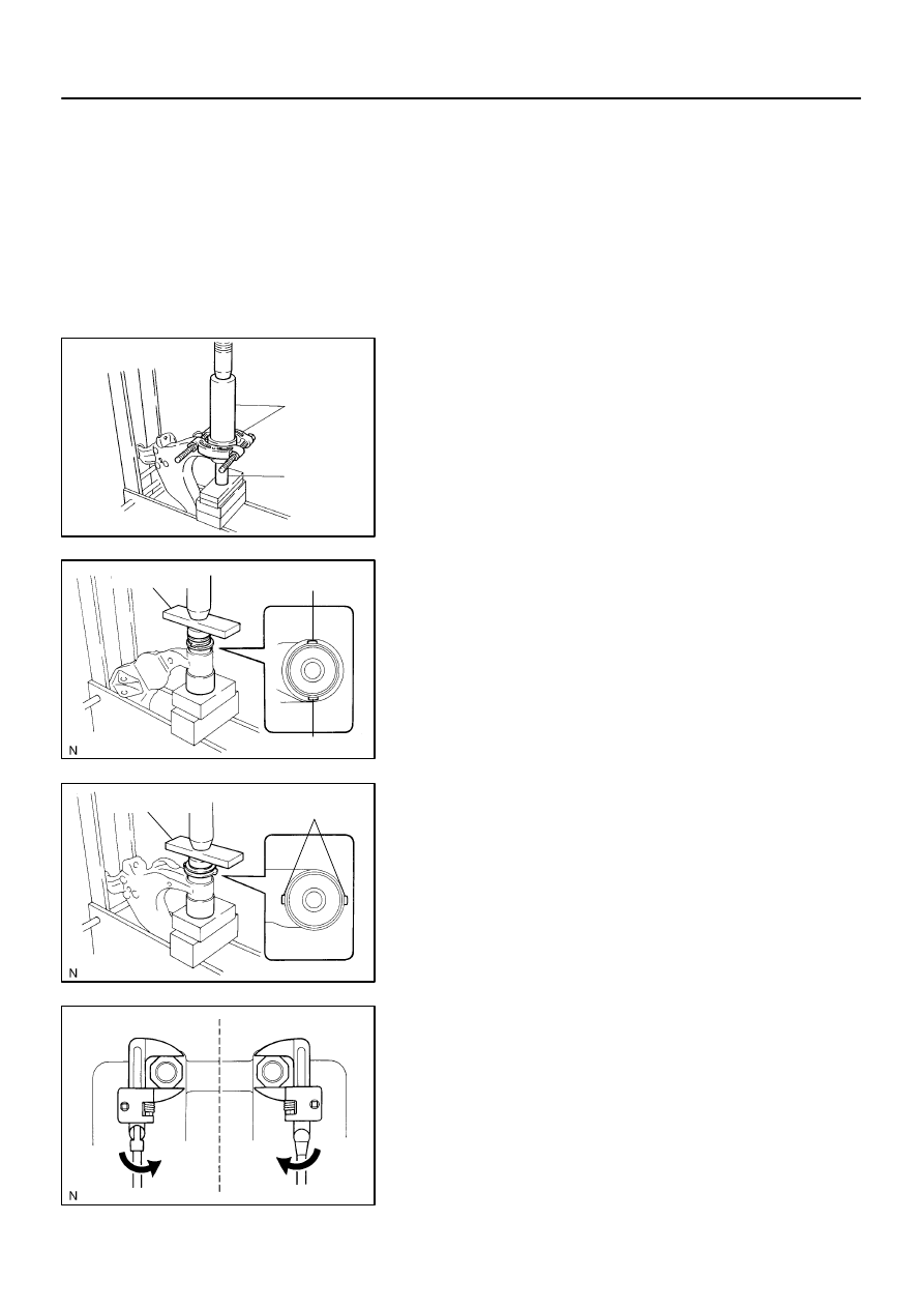
REPLACE BUSHING
(a)
Using a chisel and hammer, pry up the flange of the bush-
ing.
(b)
Using SST and a press, remove the bushing.
SST
09613–26010, 09632–36010, 09950–00020
(c)
Using SST, a press and steel plate, install a new No. 1
bushing.
SST
09502–12010, 09631–12090
HINT:
Before installing the bushing, set it in the correct direction, as
shown in the illustration.
(d)
Using SST, a press and steel plate, install a new No. 2
bushing.
SST
09631–12090, 09950–60020 (09951–00680)
HINT:
Before installing the bushing, set it in the correct direction, as
shown in the illustration.
2.
REPLACE NO. 1 AND NO. 2 SPRING BUMPERS
ON–VEHICLE
(a)
Remove the front wheel.
(b)
Using SST, replace the No. 1 spring bumper.
SST
09922–10010
HINT:
At the time of installation, use a torque wrench with a fulcrum
length of 345 mm (13.58 in.).
Torque: 23 N·m (235 kgf·cm, 17 ft·lbf)
–
SUSPENSION AND AXLE
FRONT LOWER SUSPENSION ARM
SA–79
3075
(c)
Replace the No. 2 spring bumper.
(1)
Remove the stabilizer bar (See page
).
(2)
Using SST, replace the No. 2 spring bumper.
SST
09922–10010
HINT:
At the time of installation, use a torque wrench with a fulcrum
length of 345 mm (13.58 in.).
Torque: 23 N·m (235 kgf·cm, 17 ft·lbf)
(3)
Install the stabilizer bar (See page
).
(d)
Install the front wheel.
Torque: 110 N·m (1,150 kgf·cm, 83 ft·lbf)
SA23Y–05
R13282
Matchmarks
Matchmarks
F07278
A
C
B
SA–80
–
SUSPENSION AND AXLE
FRONT LOWER SUSPENSION ARM
3076
INSTALLATION
1.
INSTALL LOWER SUSPENSION ARM TO CHASSIS
FRAME
Install the lower suspension arm with the 2 cams, bolts and cam
plates while slightly shifting the power steering gear rearward.
Torque: 130 N·m (1,325 kgf·cm, 96 ft·lbf)
NOTICE:
Do not damage the power steering gear tubes.
HINT:
After stabilizing the suspension, align the matchmarks on the
front and rear cam plates and chassis frame, and torque the
bolts.
2.
CONNECT LOWER BALL JOINT TO LOWER SUSPEN-
SION ARM
Connect the lower ball joint and install the nut and a new cotter
pin.
Torque: 159 N·m (1,621 kgf·cm, 117 ft·lbf)
If the holes for the cotter pin are not aligned, tighten the nut fur-
ther up to 60
°
.
3.
CONNECT SHOCK ABSORBER TO LOWER SUSPEN-
SION ARM
Torque: 135 N·m (1,400 kgf·cm, 100 ft·lbf)
4.
CONNECT STABILIZER BAR LINK TO LOWER SUS-
PENSION ARM
Torque: 69 N·m (700 kgf·cm, 51 ft·lbf)
HINT:
If the ball joint turns together with the nut, use a hexagon (6 mm)
wrench to hold the stud.
5.
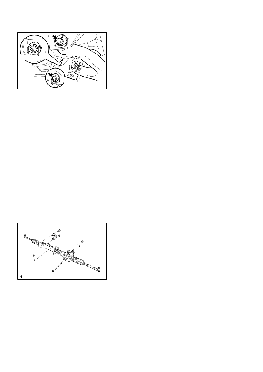
INSTALL POWER STEERING GEAR
Torque:
A bolt: 165 N·m (1,700 kgf·cm, 122 ft·lbf)
B nut: 130 N·m (1,350 kgf·cm, 96 ft·lbf)
C bolt and nut: 165 N·m (1,700 kgf·cm, 122 ft·lbf)
6.
CONNECT RH AND LH TIE ROD ENDS
Connect the RH and LH tie rod ends to the lower ball joints with
the nuts and new cotter pins.
Torque: 91 N·m (930 kgf·cm, 67 ft·lbf)
If the holes for the cotter pin are not aligned, tighten the nut fur-
ther up to 60
°
.
7.
INSTALL RH AND LH FRONT WHEELS
Torque: 110 N·m (1,150 kgf·cm, 83 ft·lbf)
8.
CHECK FRONT WHEEL ALIGNMENT (See page
9.
PERFORM ZERO POINT CALIBRATION OF STEER-
ING ANGLE, MASTER CYLINDER PRESSURE, YAW
RATE AND DECELERATION SENSORS (See page
Нет комментариевНе стесняйтесь поделиться с нами вашим ценным мнением.
Текст