Toyota Sequoia (2005). Manual — part 769
SA23V–03
F14524
F07365
Suspension
Support Bolt
25
°
25
°
LH:
RH:
Coil Spring Lower Side End
Coil Spring Lower
Side End
Front:
–
SUSPENSION AND AXLE
FRONT SHOCK ABSORBER
SA–69
3065
REASSEMBLY
1.
INSTALL COIL SPRING TO SHOCK ABSORBER
(a)
Using a spring compressor, compress the coil spring.
NOTICE:
Do not compress the coil spring more than necessary.
(b)
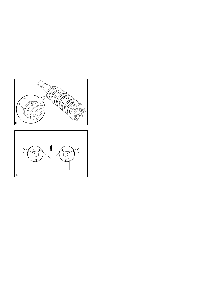
Install the coil spring to the shock absorber.
HINT:
Fit the lower end of the coil spring into the gap of the spring seat
of the shock absorber.
2.
INSTALL SUSPENSION SUPPORT
(a)
Install the cushion, 2 retainers and suspension support to
the piston rod.
(b)
Temporarily tighten a new suspension support center nut.
(c)
Position the suspension support as shown in the illustra-
tion.
NOTICE:
Do not place yourself over the top of the shock absorber.
HINT:
Recheck the direction of the suspension support.
(d)
Torque the suspension center nut.
Torque: 25 N·m (250 kgf·cm, 18 ft·lbf)
SA182–06
SA–70
–
SUSPENSION AND AXLE
FRONT SHOCK ABSORBER
3066
INSTALLATION
1.
INSTALL SHOCK ABSORBER WITH COIL SPRING
(a)
Install the upper side of the shock absorber to the chassis frame with the 3 nuts.
Torque: 64 N·m (650 kgf·cm, 47 ft·lbf)
(b)
Connect the lower side of the shock absorber to the lower suspension arm with the bolt, washer and
nut.
Torque: 135 N·m (1,400 kgf·cm, 100 ft·lbf)
2.
INSTALL FRONT WHEEL
Torque: 110 N·m (1,150 kgf·cm, 83 ft·lbf)
SA183–05
F07268
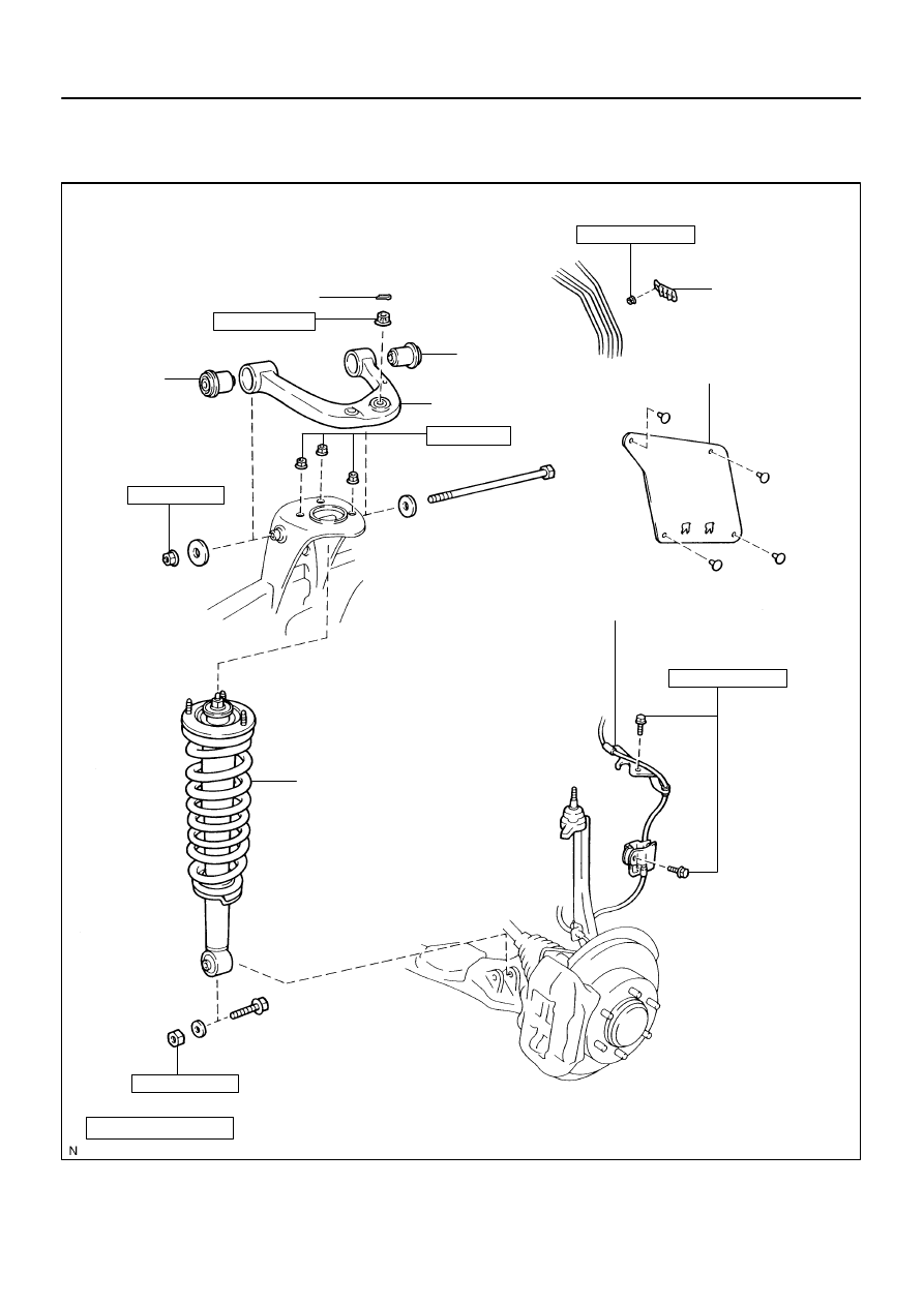
Upper Suspension Arm
N·m (kgf·cm, ft·lbf)
: Specified torque
Non–reusable part
Brake and Fuel
Line Clamp
Fender Apron Seal Rear
Speed Sensor Wire Harness
Bushing
Bushing
Cotter Pin
105 (1,100, 77)
64 (650, 47)
98 (1,000, 72)
135 (1,400, 100)
Shock Absorber
with Coil Spring
8.0 (82, 71 in.·lbf)
5.5 (56, 49 in.·lbf)
–
SUSPENSION AND AXLE
FRONT UPPER SUSPENSION ARM
SA–71
3067
FRONT UPPER SUSPENSION ARM
COMPONENTS
SA23W–03
R13196
SST
F07269
F07270
SA–72
–
SUSPENSION AND AXLE
FRONT UPPER SUSPENSION ARM
3068
REMOVAL
1.
REMOVE SHOCK ABSORBER WITH COIL SPRING
(See page
2.
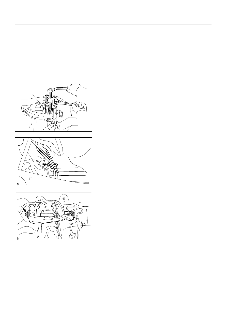
DISCONNECT SPEED SENSOR WIRE HARNESS
CLAMPS
Remove the 2 bolts and speed sensor wire harness clamps
from the steering knuckle and upper suspension arm.
3.
DISCONNECT UPPER BALL JOINT
(a)
Remove the cotter pin and loosen the nut.
(b)
Using SST, disconnect the upper ball joint.
SST
09950–40011 (09951–04010, 09952–04010,
09953–04020, 09954–04010, 09955–04031,
09958–04011)
(c)
Support the steering knuckle securely.
(d)
Remove the nut.
4.
REMOVE FENDER APRON SEAL REAR
Remove the 4 clips and fender apron seal rear.
5.
REMOVE BRAKE AND FUEL LINE CLAMP
Disengage the 2 brake lines and fuel line, and remove the nut
and brake line clamp.
6.
REMOVE UPPER SUSPENSION ARM
Remove the nut, bolt, 2 washers and upper suspension arm.
Нет комментариевНе стесняйтесь поделиться с нами вашим ценным мнением.
Текст