Toyota Sequoia (2005). Manual — part 822
R11656
SST
Wire
Cylinder End
Stopper
F06757
SST
F06758
Vinyl Tape
F08339
Oil Seal
SST
SR–50
–
STEERING
POWER STEERING GEAR
3277
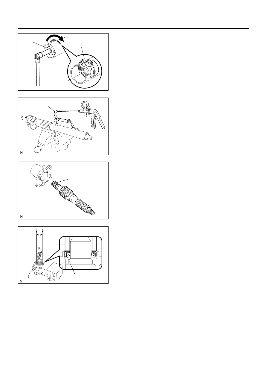
5.
INSTALL CYLINDER END STOPPER
(a)
Align the installation hole for the wire of the stopper with
the slot of the rack housing.
(b)
Install a new wire into the stopper.
(c)
Using SST, turn the stopper clockwise
400°
to 500
°
.
SST
09631–16010
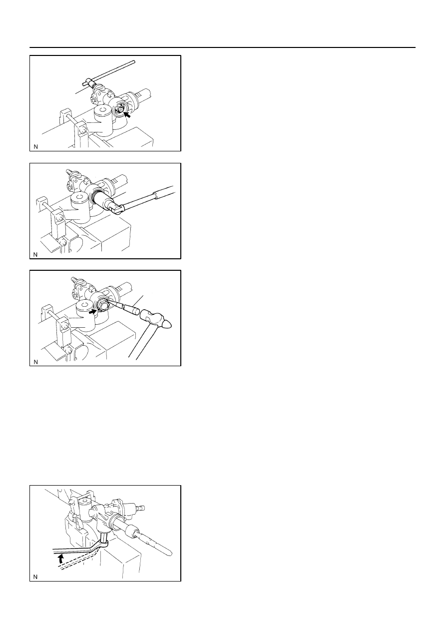
6.
AIR TIGHTNESS TEST
(a)
Install SST to the rack housing.
SST
09631–12071
(b)
Apply 53 kPa (400 mmHg, 15.75 in.Hg) of vacuum for
about 30 seconds.
(c)
Check that there is no change in the vacuum.
If there is change in the vacuum, check the installation of the oil
seals.
7.
INSTALL CONTROL VALVE ASSEMBLY
(a)
To prevent oil seal lip damage, wind vinyl tape on the ser-
rated part of the valve shaft.
(b)
Coat the teflon rings with power steering fluid.
(c)
Install the valve assembly into the valve housing.
NOTICE:
Be careful not to damage the teflon rings and oil seal.
8.
INSTALL OIL SEAL
(a)
Coat a new oil seal lip with power steering fluid.
(b)
Using SST, press in the oil seal.
SST
09612–22011
NOTICE:
Make sure to install the oil seal in the correct direction.
9.
INSTALL CONTROL VALVE HOUSING WITH CON-
TROL VALVE ASSEMBLY
(a)
Place a new gasket on the rack housing.
(b)
Align the matchmarks on the control valve housing with
the one on the rack housing.
(c)
Install the 2 bolts.
Torque: 18 N·m (185 kgf·cm, 13 ft·lbf)
F06754
SST
F06753
SST
F06759
Punch
F08342
12
°
–
STEERING
POWER STEERING GEAR
SR–51
3278
10.
INSTALL SELF–LOCKING NUT
Using SST, stop the control valve shaft rotation, install a new
nut.
SST
09616–00011
Torque: 25 N·m (250 kgf·cm, 18 ft·lbf)
11.
INSTALL DUST COVER
12.
INSTALL RACK HOUSING CAP
(a)
Apply sealant to 2 or 3 threads of the rack housing cap.
Sealant:
Part No.08833–00080, THREE BOND 1344,
LOCTITE 242 or equivalent
(b)
Using SST, install the rack housing cap.
SST
09816–30010
Torque: 59 N·m (600 kgf·cm, 43 ft·lbf)
(c)
Using a punch and hammer, stake the 2 parts of the cap.
13.
INSTALL RACK GUIDE SUB–ASSEMBLY, RACK
GUIDE SPRING AND RACK GUIDE SPRING CAP
(a)
Install the rack guide sub–assembly and rack guide
spring.
(b)
Apply sealant to 2 or 3 threads of the rack guide spring
cap.
Sealant:
Part No.08833–00080, THREE BOND 1344,
LOCTITE 242 or equivalent
(c)
Temporarily install the rack guide spring cap.
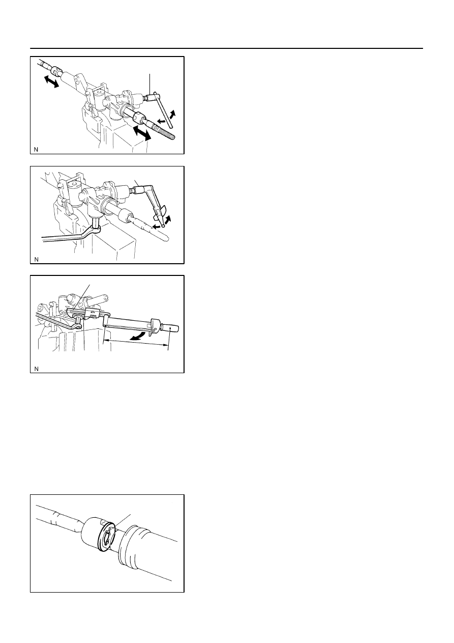
14.
ADJUST TOTAL PRELOAD
(a)
To prevent the steering rack teeth from damaging the oil
seal lip, temporarily install the RH and LH rack ends.
(b)
Using a hexagon wrench, install the rack guide spring
cap.
Torque: 25 N·m (250 kgf·cm, 18 ft·lbf)
(c)
Using a hexagon wrench, return the rack guide spring cap
12
°
.
F08330
SST
F08329
SST
F06752
SST
Rack Guide
Spring Cap Lock Nut
Fulcrum
Length
R07337
Claw
SR–52
–
STEERING
POWER STEERING GEAR
3279
(d)
Using SST, turn the control valve shaft right and left 1 or
2 turns.
SST
09616–00011
(e)
Using a hexagon wrench, loosen the rack guide spring
cap until the rack guide spring does not functioning.
(f)
Using SST, torque wrench and hexagon wrench, tighten
the rack guide spring cap until the preload becomes with-
in specification.
SST
09616–00011
Preload (turning):
1.2 to 1.6 N·m (12 to 16 kgf·cm, 10.4 to 13.9 in.·lbf)
15.
INSTALL RACK GUIDE SPRING CAP LOCK NUT
(a)
Apply sealant to 2 or 3 threads of the lock nut.
Sealant:
Part No.08833–00080, THREE BOND 1344,
LOCTITE 242 or equivalent
(b)
Temporarily install the lock nut.
(c)
Using a hexagon wrench, hold the rack guide spring cap,
and using SST, tighten the lock nut.
SST
09922–10010
Torque: 44 N·m (450 kgf·cm, 32 ft·lbf)
NOTICE:
Use SST in the direction shown in the illustration.
SST
09922–10010
HINT:
Use a torque wrench with a fulcrum length of 345 mm (13.58
in.).
(d)
Recheck the total preload.
Preload (turning):
1.2 to 1.6 N·m (12 to 16 kgf·cm, 10.4 to 13.9 in.·lbf)
(e)
Remove the RH and LH rack ends.
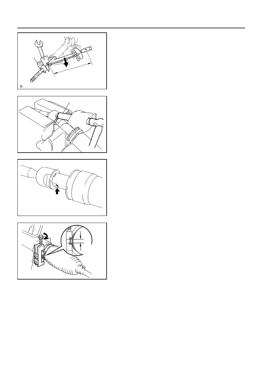
16.
INSTALL RH AND LH CLAW WASHERS AND RACK
ENDS
(a)
Install a new claw washer, and temporarily install the rack
end.
HINT:
Align the claws of the claw washer with the steering rack
grooves.
F06750
Fulcrum Length
SST
R06400
Brass Bar
W01261
W04223
3 mm
(0.12 in.)
or less
SST
–
STEERING
POWER STEERING GEAR
SR–53
3280
(b)
Using a spanner, hold the steering rack steady, and using
SST, tighten the rack end.
SST
09922–10010
Torque: 76 N·m (770 kgf·cm, 56 ft·lbf)
NOTICE:
Use SST in the direction shown in the illustration.
SST
09922–10010
HINT:
Use a torque wrench with a fulcrum length of 345 mm (13.58
in.).
(c)
Using a brass bar and hammer, stake the washer.
NOTICE:
Avoid any impact on the rack.
(d)
Perform the same procedure on the other side.
17.
INSTALL RH AND LH RACK BOOTS, CLAMPS AND
CLIPS
(a)
Ensure that the steering rack hole is not clogged with
grease.
HINT:
If the hole is clogged, the pressure inside the boot will change
after it is assembled and the steering wheel is turned.
(b)
Set a new clamp to the groove of the rack boot.
(c)
Install the boot.
NOTICE:
Be careful not to damage or twist the boot.
(d)
Using SST, tighten the clamp as shown in the illustration.
SST
09521–24010
(e)
Install the clip to the rack boot.
(f)
Perform the same procedure on the other side.
18.
INSTALL RH AND LH TIE ROD ENDS AND LOCK NUTS
(a)
Screw the lock nut and tie rod end onto the rack end until
the matchmarks are aligned.
(b)
After adjusting toe–in, tighten the nut
(See page
Torque: 55 N·m (560 kgf·cm, 41 ft·lbf)
Нет комментариевНе стесняйтесь поделиться с нами вашим ценным мнением.
Текст