Toyota Sequoia (2005). Manual — part 659
EM1X1–01
A03194
A03193
EM6323
EM6324
P21861
EM–46
–
ENGINE MECHANICAL
CYLINDER HEAD
2625
INSPECTION
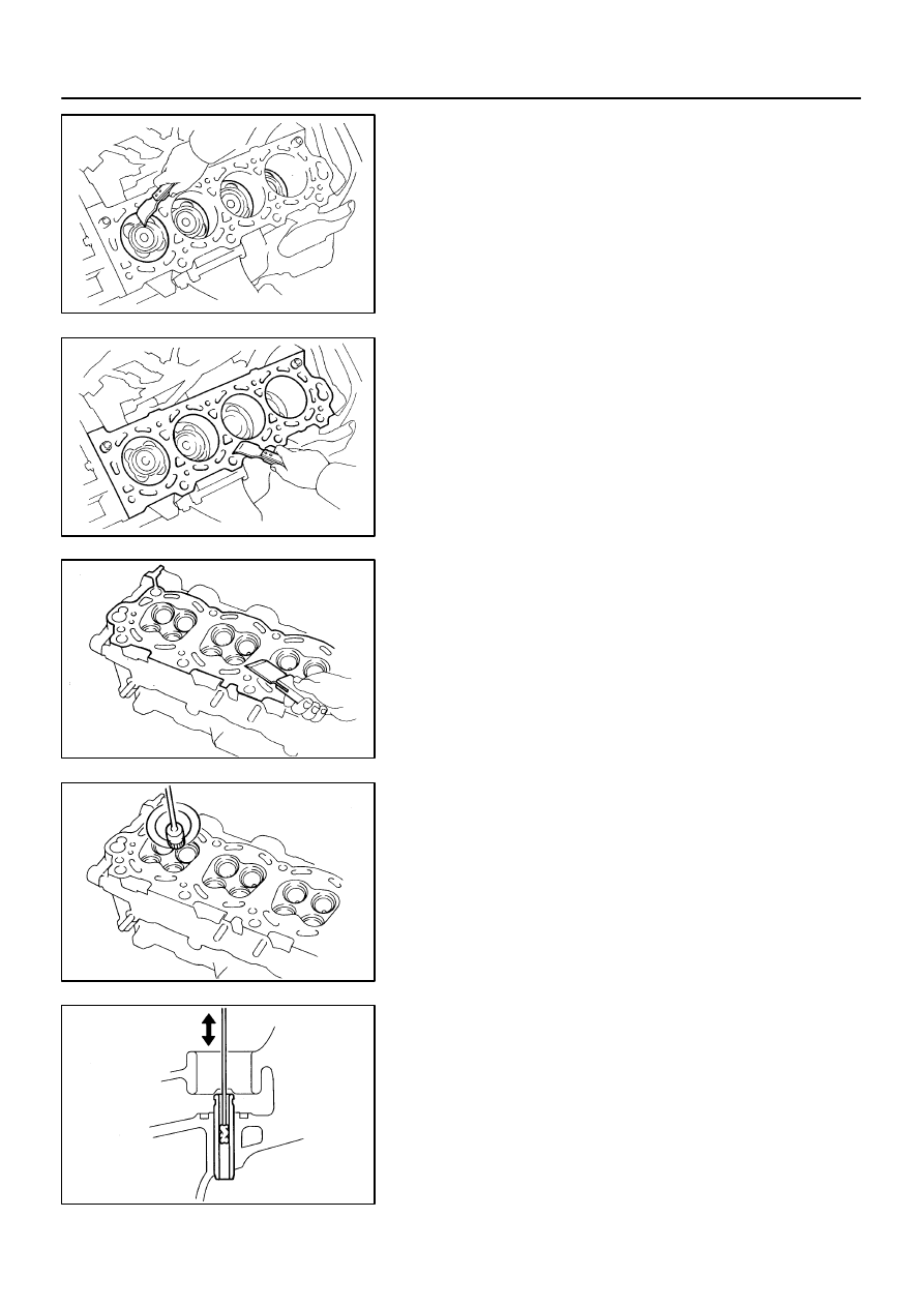
1.
CLEAN TOP SURFACES OF PISTONS AND CYL-
INDER BLOCK
(a)
Turn the crankshaft, and bring each piston to top dead
center (TDC). Using a gasket scraper, remove all the car-
bon from the piston top surface.
(b)
Using a surface contacting gasket scraper, remove all the
gasket materials from the cylinder block.
(c)
Using compressed air, blow carbon and oil from the bolt
holes.
CAUTION:
Protect your eyes when using high pressure compressed
air.
2.
REMOVE GASKET MATERIAL
Using a gasket scraper, remove all the gasket material from the
cylinder block contact surface.
NOTICE:
Be careful not to scratch the surface contacting the cylin-
der block.
3.
CLEAN COMBUSTION CHAMBERS
Using a wire brush, remove all the carbon from the combustion
chambers.
NOTICE:
Be careful not to scratch the surface contacting the cylin-
der block.
4.
CLEAN VALVE GUIDE BUSHINGS
Using a valve guide bushing brush and solvent, clean all the
guide bushings.
EM6325
A05592
EM6327
A21018
50 mm
(1.96 in.)
Measuring
Point
–
ENGINE MECHANICAL
CYLINDER HEAD
EM–47
2626
5.
CLEAN CYLINDER HEAD
Using a soft brush and solvent, thoroughly clean the cylinder
head.
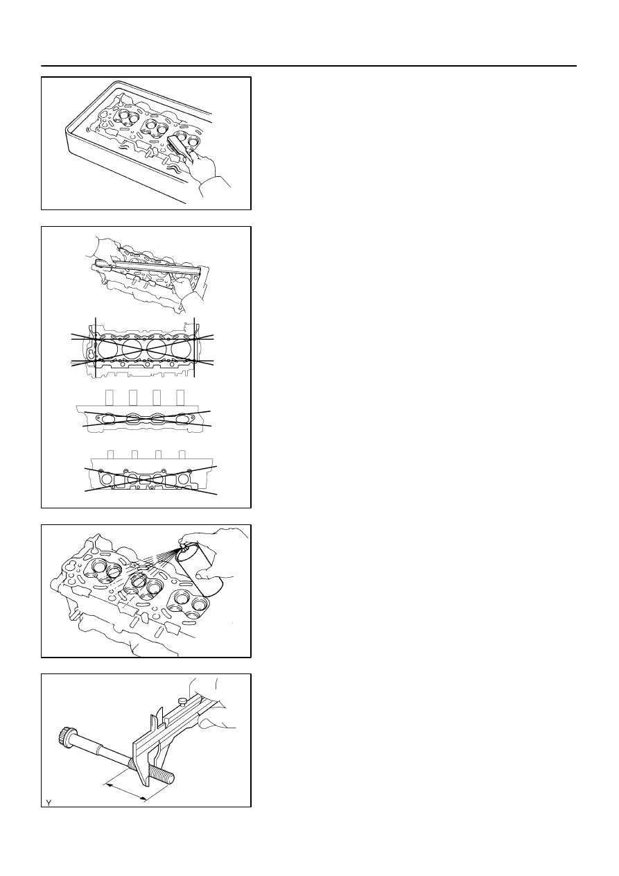
6.
INSPECT FOR FLATNESS
Using a precision straight edge and feeler gauge, measure the
surfaces contacting the cylinder block and the manifolds for
warpage.
Maximum warpage: 0.10 mm (0.0039 in.)
If warpage is greater than maximum, replace the cylinder head.
7.
INSPECT FOR CRACKS
Using a dye penetrate, check the combustion chamber, intake
ports, exhaust ports and cylinder block surface for cracks.
If cracked, replace the cylinder head.
8.
INSPECT CYLINDER HEAD BOLT
Using vernier calipers, measure the thread outside diameter of
the cylinder head bolt.
Standard outside diameter:
9.810 to 9.960 mm (0.3862 to 0.3921 in.)
Minimum outside diameter: 9.70 mm (0.3819 in.)
If the diameter is less than minimum, replace the bolt.
EM0580
A04087
A04091
A04236
Z00052
Z00054
44.5
°
EM–48
–
ENGINE MECHANICAL
CYLINDER HEAD
2627
9.
CLEAN VALVES
(a)
Using a gasket scraper, chip off any carbon from the valve
head.
(b)
Using a wire brush, thoroughly clean the valve.
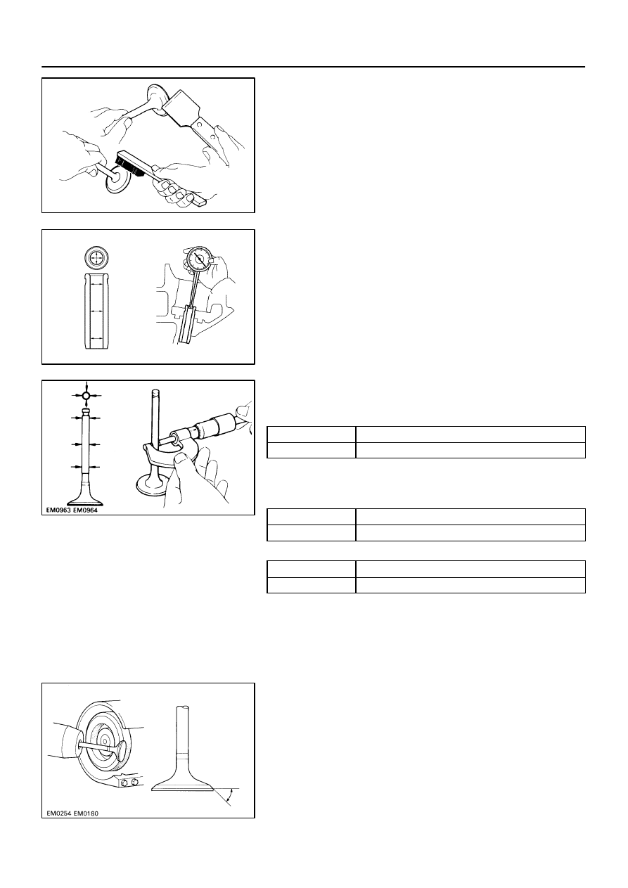
10.
INSPECT VALVE STEMS AND GUIDE BUSHINGS
(a)
Using a caliper gauge, measure the inside diameter of the
guide bushing.
Bushing inside diameter:
5.510 to 5.530 mm (0.2169 to 0.2177 in.)
(b)
Using a micrometer, measure the diameter of the valve
stem.
Valve stem diameter:
Intake
5.470 to 5.485 mm (0.2154 to 0.2159 in.)
Exhaust
5.465 to 5.480 mm (0.2152 to 0.2157 in.)
(c)
Subtract the valve stem diameter measurement from the
guide bushing inside diameter measurement.
Standard oil clearance:
Intake
0.025 to 0.060 mm (0.0010 to 0.0024 in.)
Exhaust
0.030 to 0.065 mm (0.0012 to 0.0026 in.)
Maximum oil clearance:
Intake
0.08 mm (0.0031 in.)
Exhaust
0.10 mm (0.0039 in.)
If the clearance is greater than maximum, replace the valve and
guide bushing. (See page
11.
INSPECT AND GRIND VALVES
(a)
Grind the valve enough to remove pits and carbon.
(b)
Check that the valve is ground to the correct valve face
angle.
Valve face angle: 44.5
°
EM0181
Margin Thickness
EM2534
Overall Length
EM0255
EM6330
45
°
Carbide Cutter
Z00055
Width
–
ENGINE MECHANICAL
CYLINDER HEAD
EM–49
2628
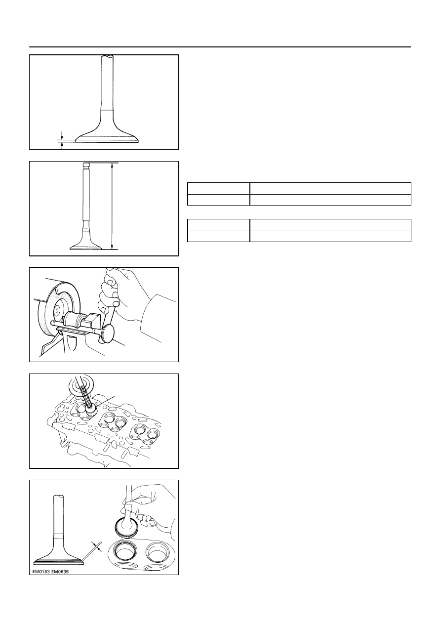
(c)
Check the valve head margin thickness.
Standard margin thickness: 1.0 mm (0.039 in.)
Minimum margin thickness: 0.5 mm (0.020 in.)
If the margin thickness is less than minimum, replace the valve.
(d)
Check the valve overall length.
Standard overall length:
Intake
95.05 mm (3.7421 in.)
Exhaust
95.10 mm (3.7441 in.)
Minimum overall length:
Intake
94.55 mm (3.7224 in.)
Exhaust
94.60 mm (3.7244 in.)
If the overall length is less than minimum, replace the valve.
(e)
Check the surface of the valve stem tip for wear.
If the valve stem tip is worn, resurface the tip with a grinder or
replace the valve.
NOTICE:
Do not grind off more than minimum.
12.
INSPECT AND CLEAN VALVE SEATS
(a)
Using a 45
°
carbide cutter, resurface the valve seats. Re-
move only metal enough to clean the seats.
(b)
Check the valve seating position.
Apply a light coat of Prussian blue (or white lead) to the
valve face. Lightly press the valve against the seat. Do not
rotate the valve.
Нет комментариевНе стесняйтесь поделиться с нами вашим ценным мнением.
Текст