Toyota Sequoia (2005). Manual — part 657
A23328
A23329
A23330
(a)
(a)
(b)
(c)
(c)
(c)
B17510
A23331
EM–38
–
ENGINE MECHANICAL
CYLINDER HEAD
2617
(f)
Disconnect the engine wire from the engine hanger and
wire bracket.
(g)
Remove the wire bracket from the intake manifold.
(h)
Remove the 6 bolts, 4 nuts, intake manifold assembly and
2 gaskets.
15.
DISASSEMBLE INTAKE MANIFOLD
(a)
Remove the 2 bolts and VSVs for the air injection system.
(b)
Disconnect the EVAP hose from the upper intake man-
ifold, and remove the VSV for EVAP.
(c)
Remove the bolt, 2 unions, 4 gaskets and front fuel pipe
from the intake manifold.
(d)
Remove the throttle body (see page
).
(e)
Remove the bolt and VSV for ACIS from the intake man-
ifold.
(f)
Disconnect the fuel return hose from the fuel pressure
regulator.
(g)
Remove the 3 bolts and fuel return pipe from the intake
manifold.
(h)
Remove the 2 bolts, fuel pressure regulator and O–ring.
(i)
Remove the fuel pressure pulsation damper and 2 gas-
kets.
(j)
Remove the 2 delivery pipes and 8 injectors (see page
A23332
Front Water Bypass Joint
A23333
Rear Water Bypass Joint
A05564
–
ENGINE MECHANICAL
CYLINDER HEAD
EM–39
2618
16.
REMOVE WATER INLET AND INLET HOUSING AS-
SEMBLY (See page
)
17.
REMOVE AIR PUMP ASSEMBLY (See page
18.
REMOVE NO.2 AIR SWITCHING VALVES
(See page
19.
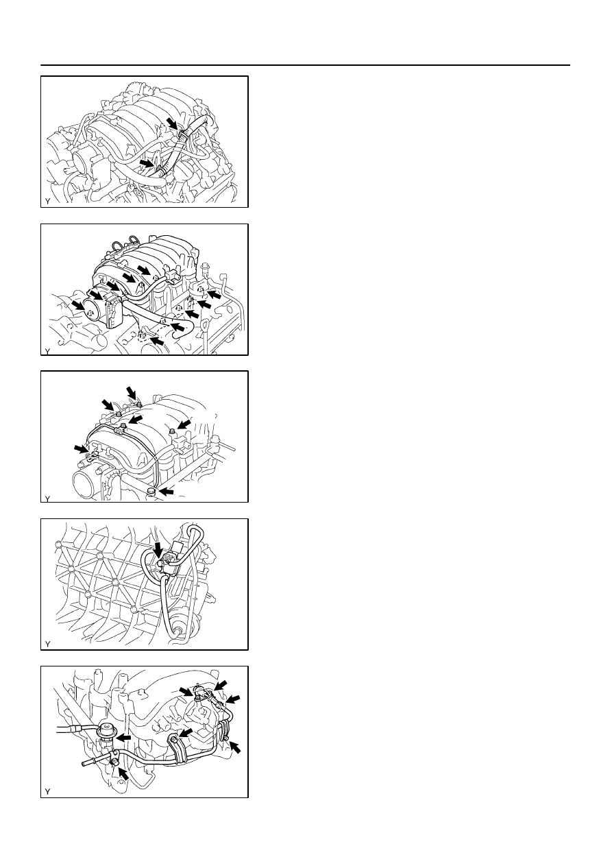
REMOVE FRONT WATER BYPASS JOINT
Remove the 4 nuts, water bypass joint and 2 gaskets.
20.
REMOVE REAR WATER BYPASS JOINT
Remove the 4 nuts, water bypass joint and 2 gaskets.
21.
REMOVE ENGINE HANGERS
22.
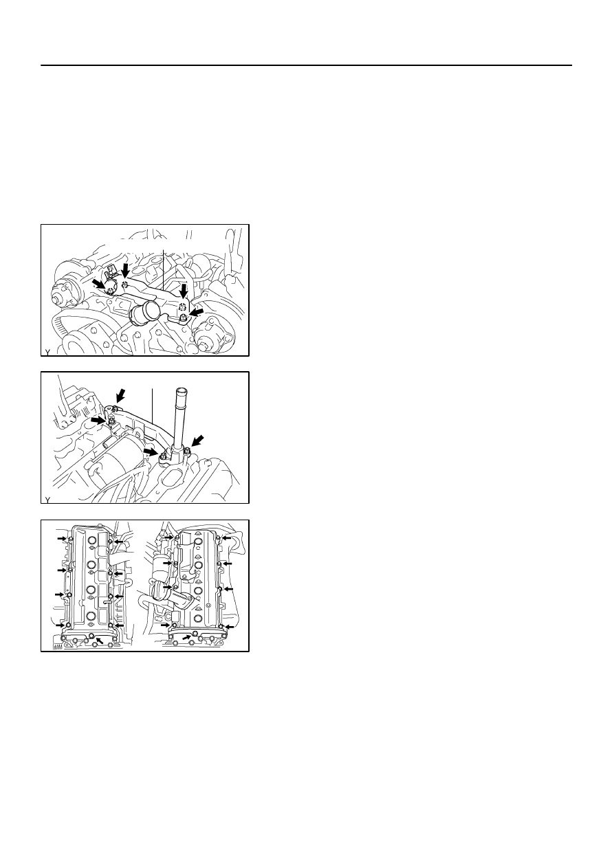
REMOVE CYLINDER HEAD COVERS
Remove the 18 bolts, seal washers, RH and LH cylinder head
covers and 2 gaskets.
23.
IF NECESSARY, REMOVE SEMI–CIRCULAR PLUGS
AND CAMSHAFT HOUSING PLUGS
24.
REMOVE CAMSHAFTS
NOTICE:
Since the thrust clearance of the camshaft is small, the
camshaft must be kept level while it is being removed. If the
camshaft is not kept level, the portion of the cylinder head
receiving the shaft thrust may crack or be damaged, caus-
ing the camshaft to seize or break. To avoid this, the follow-
ing steps should be carried out.
A04456
No.2 Idler
Pulley Bolt
Timing
Mark
Crankshaft
Pulley Bolt
A23334
Movement
(25
°
)
SST
Oil Control Valve
Installation Hole
A23335
Service Bolt
A23336
EM–40
–
ENGINE MECHANICAL
CYLINDER HEAD
2619
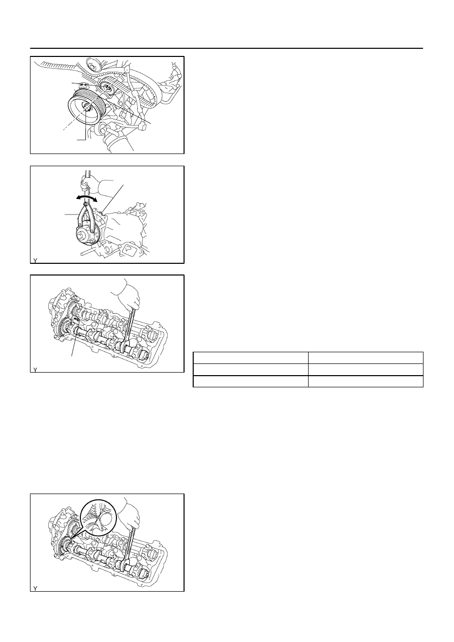
(a)
Check the crankshaft pulley position.
Check that the timing mark of the crankshaft pulley is
aligned with the centers of the crankshaft pulley bolt and
idler pulley bolt.
NOTICE:
Having the crankshaft pulley at the wrong angle can cause
the piston head and valve head to come into contact with
each other when you remove the camshaft, causing dam-
age. So always set the crankshaft pulley at the correct
angle.
(b)
Release the oil from the front bearing caps.
Using SST, rotate the camshaft timing tube from left to
right 2 to 3 times within its VVT–i range (25
°
) and use a
waste cloth to collect the oil from the camshaft timing oil
control valve installation hole.
SST
09960–10010 (09962–01000, 09963–00400)
NOTICE:
Approximately 20 cc (1.2 cu in.) of oil will be ejected. Take
care not to spill it.
(c)
Remove the LH camshafts.
(1)
Bring the service bolt hole of the sub–gear upward
by turning the hexagon head portion of the exhaust
camshaft with a wrench.
(2)
Secure the sub–gear to the main gear with a service
bolt.
Recommended service bolt:
Thread diameter
6 mm
Thread pitch
1.0 mm
Bolt length
16 to 20 mm (0.63 to 0.79 in.)
HINT:
When removing the camshaft, make sure that the torsional
spring force of the sub–gear has been eliminated by the above
operation.
(3)
Align the timing mark (2–dot mark) of the camshaft
drive gear by turning the hexagon head portion of
the exhaust camshaft with a wrench.
A23337
1
2
3
4
5
6
7
8
11
12
13
14
15
16
17
18
21
22
9
10
19
20
A23338
Service Bolt
A23339
Approx.
10
°
A23340
1
2
21
22
19
20
7
8
11
12
13
14
15
16
3
4
17
18
5
6
9
10
–
ENGINE MECHANICAL
CYLINDER HEAD
EM–41
2620
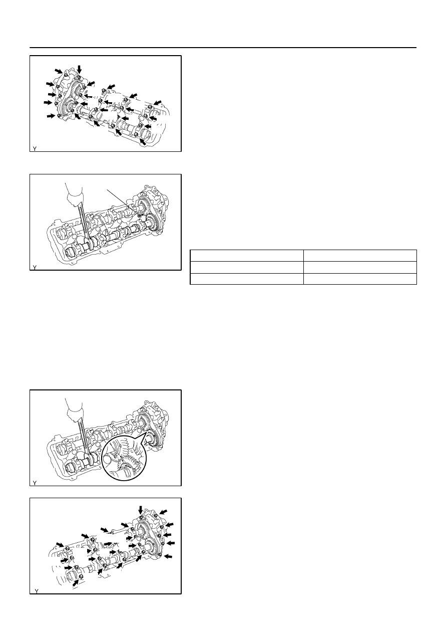
(4)
Uniformly loosen the 22 bearing cap bolts in several
steps, in the sequence shown.
(5)
Remove the 22 bearing cap bolts, 4 seal washers,
oil feed pipe, 9 bearing caps, camshaft housing
plug, oil control valve filter and 2 camshafts.
(d)
Remove the RH camshafts.
(1)
Bring the service bolt hole of the sub–gear upward
by turning the hexagon head portion of the exhaust
camshaft with a wrench.
(2)
Secure the sub–gear to the main gear with a service
bolt.
Recommended service bolt:
Thread diameter
6 mm
Thread pitch
1.0 mm
Bolt length
16 to 20 mm (0.63 to 0.79 in.)
HINT:
When removing the camshafts, make sure that the torsional
spring force of the sub–gear has been eliminated by the above
operation.
(3)
Set the timing mark (1–dot mark) of the camshaft
main gear at approx. 10
°
angle by turning the hexa-
gon head portion of the exhaust camshaft with a
wrench.
(4)
Uniformly loosen the 22 bearing cap bolts in several
steps, in the sequence shown.
(5)
Remove the 22 bearing cap bolts, 4 seal washers,
oil feed pipe, 9 bearing caps, camshaft housing
plug, strainer and 2 camshafts.
HINT:
Arrange the bearing caps for RH and LH sides.
Нет комментариевНе стесняйтесь поделиться с нами вашим ценным мнением.
Текст