Toyota Sequoia (2005). Manual — part 574

–
DIAGNOSTICS
REAR SEAT ENTERTAINMANT SYSTEM
DI–2091
2285
R–L– – GND
(R23–23 – R23–29)
W – Y
Sound signal (Input)
RSE system is playing
A waveform
synchronized
with sound is
output
R–L+ – GND
(R23–24 – R23–29)
W – Y
Sound signal (Input)
RSE system is playing
A waveform
synchronized
with sound is
output
R–R– – GND
(R23–25 – R23–29)
W – Y
Sound signal (Input)
RSE system is playing
A waveform
synchronized
with sound is
output
R–R+ – GND
(R23–26 – R23–29)
W – Y
Sound signal (Input)
RSE system is playing
A waveform
synchronized
with sound is
output
SG2 – Body ground
(R23–27 – Body ground)
Shielded – Body ground
Ground
Always
Below 1 V
RMUT – GND
(R23–28 – R23–29)
LG – Y
Mute signal
Audio source is changing
Below 1 V
GND – Body ground
(R23–29 – Body ground)
Y – Body ground
Ground
Always
Below 1 V
TX– – GND
(R23–30 – R23–29)
LG – Y
AVC–LAN
communication signal
Ignition switch ACC
2 to 3 V
TX+ – GND
(R23–31 – R23–29)
LG – Y
AVC–LAN
communication signal
Ignition switch ACC
2 to 3 V
ACC – GND
(R23–32 – R23–29)
LG – Y
Ignition (ACC)
Ignition switch in the ACC position
10 to 14 V
MUTE – GND
(R22–1 – R23–29)
LG – Y
Mute signal
Disc player controller is changing
Below 1 V
AL– – GND
(R22–2 – R23–29)
W – Y
Sound signal (Input)
DVD system is playing
A waveform
synchronized
with sound is
output
AL+ – GND
(R22–3 – R23–29)
W – Y
Sound signal (Input)
DVD system is playing
A waveform
synchronized
with sound is
output
AR– – GND
(R22–4 – R23–29)
W – Y
Sound signal (Input)
DVD system is playing
A waveform
synchronized
with sound is
output
AR+ – GND
(R22–5 – R23–29)
W – Y
Sound signal (Input)
DVD system is playing
A waveform
synchronized
with sound is
output
SG4 – Body ground
(R22–6 – Body ground)
Shielded – Body ground
Ground
Always
Below 1 V
NTS2 – GND
(R22–8 – R23–29)
BR – Y
Display signal
DVD system is displayed
Pulse genera-
tion
SGN2 – Body ground
(R22–9 – Body ground)
BR – Body ground
Ground
Always
Below 1 V
SG9 – Body ground
(R22–10 – Body ground)
Shielded – Body ground
Ground
Always
Below 1 V
+B – GND
(R22–11 – R23–29)
LG – Y
Battery
Always
10 to 14 V

DI–2092
–
DIAGNOSTICS
REAR SEAT ENTERTAINMANT SYSTEM
2286
ACC3 – GND
(R22–12 – R23–29)
LG – Y
Ignition (ACC)
Ignition switch in the ACC position
10 to 14 V
TX3– – GND
(R22–13 – R23–29)
LG – Y
AVC–LAN
communication signal
Ignition switch ACC
2 to 3 V
TX3+ – GND
(R22–14 – R23–29)
LG – Y
AVC–LAN
communication signal
Ignition switch ACC
2 to 3 V
GND4 – Body ground
(R22–15 – Body ground)
LG – Body ground
Ground
Always
Below 1 V
HPL– – GND
(R22–16 – R23–29)
W – Y
Sound signal (Output)
RSE system is playing
A waveform
synchronized
with sound is
output
HPL+ – GND
(R22–17 – R23–29)
W – Y
Sound signal (Output)
RSE system is playing
A waveform
synchronized
with sound is
output
HPR– – GND
(R22–18 – R23–29)
W – Y
Sound signal (Output)
RSE system is playing
A waveform
synchronized
with sound is
output
HPR+ – GND
(R22–19 – R23–29)
W – Y
Sound signal (Output)
RSE system is playing
A waveform
synchronized
with sound is
output
SLD1 – Body ground
(R22–20 – Body ground)
Shielded – Body ground
Ground
Always
Below 1 V
+B2 – GND
(R21–1 – R23–29)
Y – Y
Battery
Always
10 to 14 V
ACC2 – GND
(R21–2 – R23–29)
LG – Y
Ignition (ACC)
Ignition switch in the ACC position
10 to 14 V
GAUX – GND
(R21–3 – R23–29)
LG – Y
Ground
External device system is playing
(At that time of VTR jack use)
A waveform
synchronized
with sound is
output
TX2– – GND
(R21–4 – R23–29)
LG – Y
AVC–LAN
communication signal
Ignition switch ACC
2 to 3 V
TX2+ – GND
(R21–5 – R23–29)
LG – Y
AVC–LAN
communication signal
Ignition switch ACC
2 to 3 V
GND1 – Body ground
(R21–6 – Body ground)
Y – Body ground
Ground
Always
Below 1 V
SG5 – Body ground
(R21–7 – Body ground)
Shielded – Body ground
Ground
Always
Below 1 V
HP1L – GND
(R21–8 – R23–29)
BR – Y
Sound signal (Input)
External device system is playing
(At that time of VTR jack use)
A waveform
synchronized
with sound is
output
HP1R – GND
(R21–9 – R23–29)
BR – Y
Sound signal (Input)
External device system is playing
(At that time of VTR jack use)
A waveform
synchronized
with sound is
output
SG7 – Body ground
(R21–10 – Body ground)
Shielded – Body ground
Ground
Always
Below 1 V
AUXL – GND
(R21–11 – R23–29)
BR – Y
Sound signal
External device system is playing
(At that time of VTR jack use)
A waveform
synchronized
with sound is
output
I28286
R25
–
DIAGNOSTICS
REAR SEAT ENTERTAINMANT SYSTEM
DI–2093
2287
AUXR – GND
(R21–12 – R23–29)
BR – Y
Sound signal
External device system is playing
(At that time of VTR jack use)
A waveform
synchronized
with sound is
output
R2 – GND
(R21–13 – R23–29)
B – Y
Display signal (Red)
Display is on
(Television display assy)
Pulse genera-
tion
G2 – GND
(R21–14 – R23–29)
B – Y
Display signal (Green)
Display is on
(Television display assy)
Pulse genera-
tion
B2 – GND
(R21–15 – R23–29)
B – Y
Display signal (Blue)
Display is on
(Television display assy)
Pulse genera-
tion
SYN2 – GND
(R21–16 – R23–29)
B – Y
Display signal
(Synchronize)
Display is on
(Television display assy)
Pulse genera-
tion
VR2 – Body ground
(R21–17 – Body ground)
B – Body ground
Ground
Always
Below 1 V
VG2 – Body ground
(R21–18 – Body ground)
Shielded – Body ground
Ground
Always
Below 1 V
SG6 – Body ground
(R21–19 – Body ground)
Shielded – Body ground
Ground
Always
Below 1 V
HP2L – GND
(R21–20 – R23–29)
BR – Y
Sound signal (Output)
Audio system is playing (Head-
phone)
A waveform
synchronized
with sound is
output
HP2R – GND
(R21–21 – R23–29)
BR – Y
Sound signal (Output)
Audio system is playing (Head-
phone)
A waveform
synchronized
with sound is
output
SG6 – Body ground
(R21–22 – Body ground)
Shielded – Body ground
Ground
Always
Below 1 V
SGN5 – Body ground
(R21–23 – Body ground)
BR – Body ground
Ground
Always
Below 1 V
NTS4 – GND
(R21–24 – R23–29)
BR – Y
Display signal
External device system displayed
(At that time of VTR jack use)
Pulse genera-
tion
*1: w/ Navigation System
2.
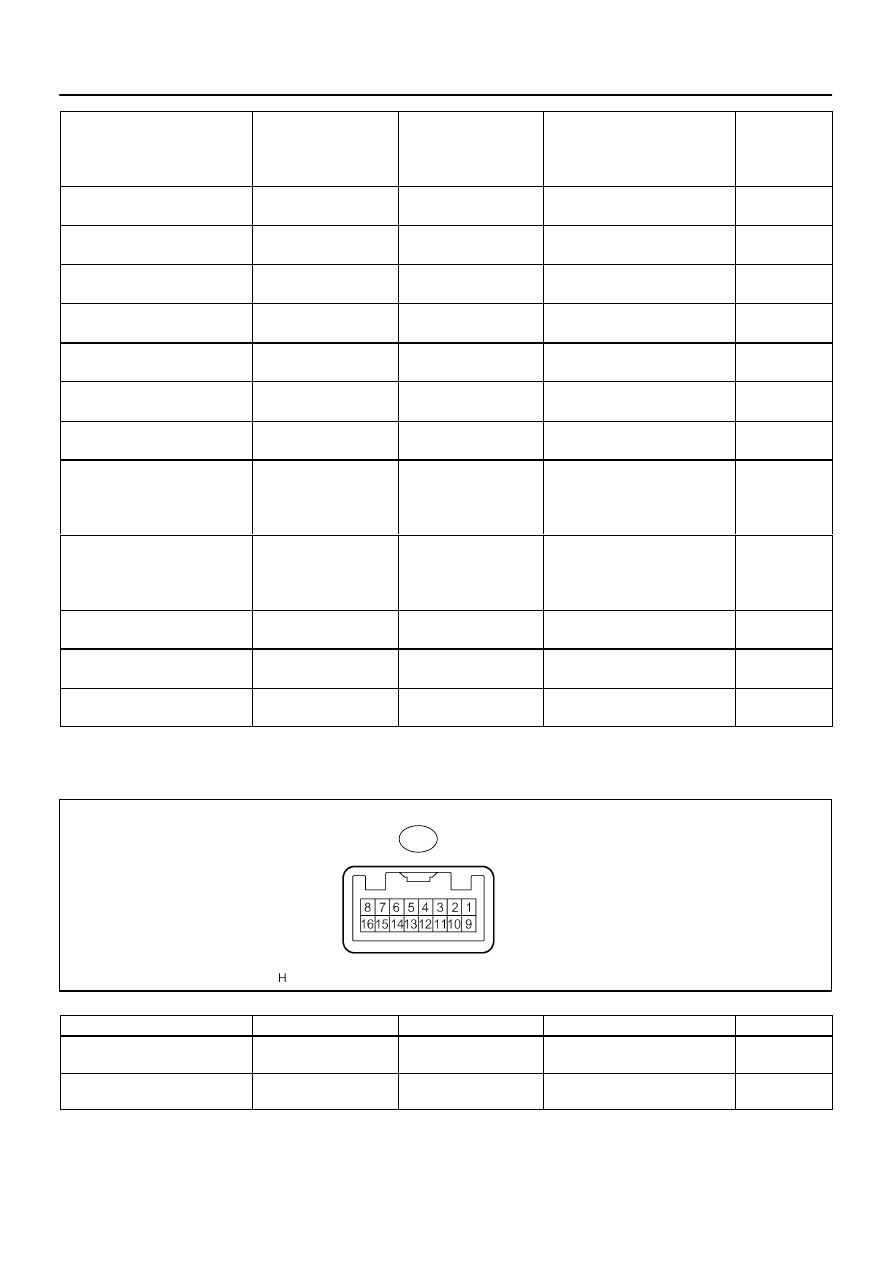
TELEVISION DISPLAY ASSY
Symbols (Terminals No.)
Wiring Color
Terminal Description
Condition
Specification
GND – Body ground
(R25–1 – Body ground)
Y – Body ground
Ground
Always
Below 1 V
SGND – Body ground
(R25–2 – Body ground)
Shielded – Body ground
Ground
Always
Below 1 V
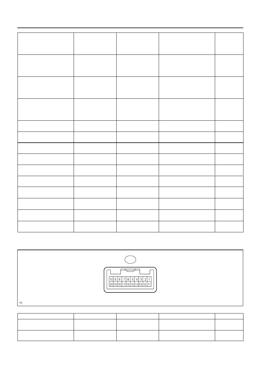
I28287
D23
DI–2094
–
DIAGNOSTICS
REAR SEAT ENTERTAINMANT SYSTEM
2288
R+ – GND
(R25–3 – R25–1)
W – Y
Sound signal (Input)
RSE system is sounding (Head-
phone)
A waveform
synchronized
with sound is
output
R– – GND
(R25–4 – R25–1)
W – Y
Sound signal (Input)
RSE system is sounding (Head-
phone)
A waveform
synchronized
with sound is
output
L+ – GND
(R25–5 – R25–1)
W – Y
Sound signal (Input)
RSE system is sounding (Head-
phone)
A waveform
synchronized
with sound is
output
L– – GND
(R25–6 – R25–1)
W – Y
Sound signal (Input)
RSE system is sounding (Head-
phone)
A waveform
synchronized
with sound is
output
ACC – GND
(R25–7 – R25–1)
LG – Y
Ignition (ACC)
Ignition switch ACC
10 to 14 V
BU+B – GND
(R25–8 – R25–1)
Y – Y
Battery
Always
10 to 14 V
TX+ – GND
(R25–9 – R25–1)
LG – Y
AVC–LAN
communication signal
Ignition switch ACC
2 to 3 V
TX– – GND
(R25–10 – R25–1)
LG – Y
AVC–LAN
communication signal
Ignition switch ACC
2 to 3 V
VG – Body ground
(R25–11 – Body ground)
Shielded – Body ground
Ground
Always
Below 1 V
VR – Body ground
(R25–12 – Body ground)
B – Body ground
Ground
Always
Below 1 V
SYNC – VR
(R25–13 – R25–12)
B – B
Display signal
(Synchronize)
Rear display is displayed
Pulse genera-
tion
B – VR
(R25–14 – R25–12)
B – B
Display signal (Blue)
Rear display is displayed
Pulse genera-
tion
G – VR
(R25–15 – R25–12)
B – B
Display signal (Green)
Rear display is displayed
Pulse genera-
tion
R – VR
(R25–16 – R25–12)
B – B
Display signal (Red)
Rear display is displayed
Pulse genera-
tion
3.
DISC PLAYER CONTROLLER
Symbols (Terminals No.)
Wiring Color
Terminal Description
Condition
Specification
SLD – Body ground
(D23–1 – Body ground)
Shielded – Body ground
Ground
Always
Below 1 V
S.GND – Body ground
(D23–2 – Body ground)
BR – Body ground
Ground
Always
Below 1 V
Нет комментариевНе стесняйтесь поделиться с нами вашим ценным мнением.
Текст