Toyota Sequoia (2005). Manual — part 819
F06761
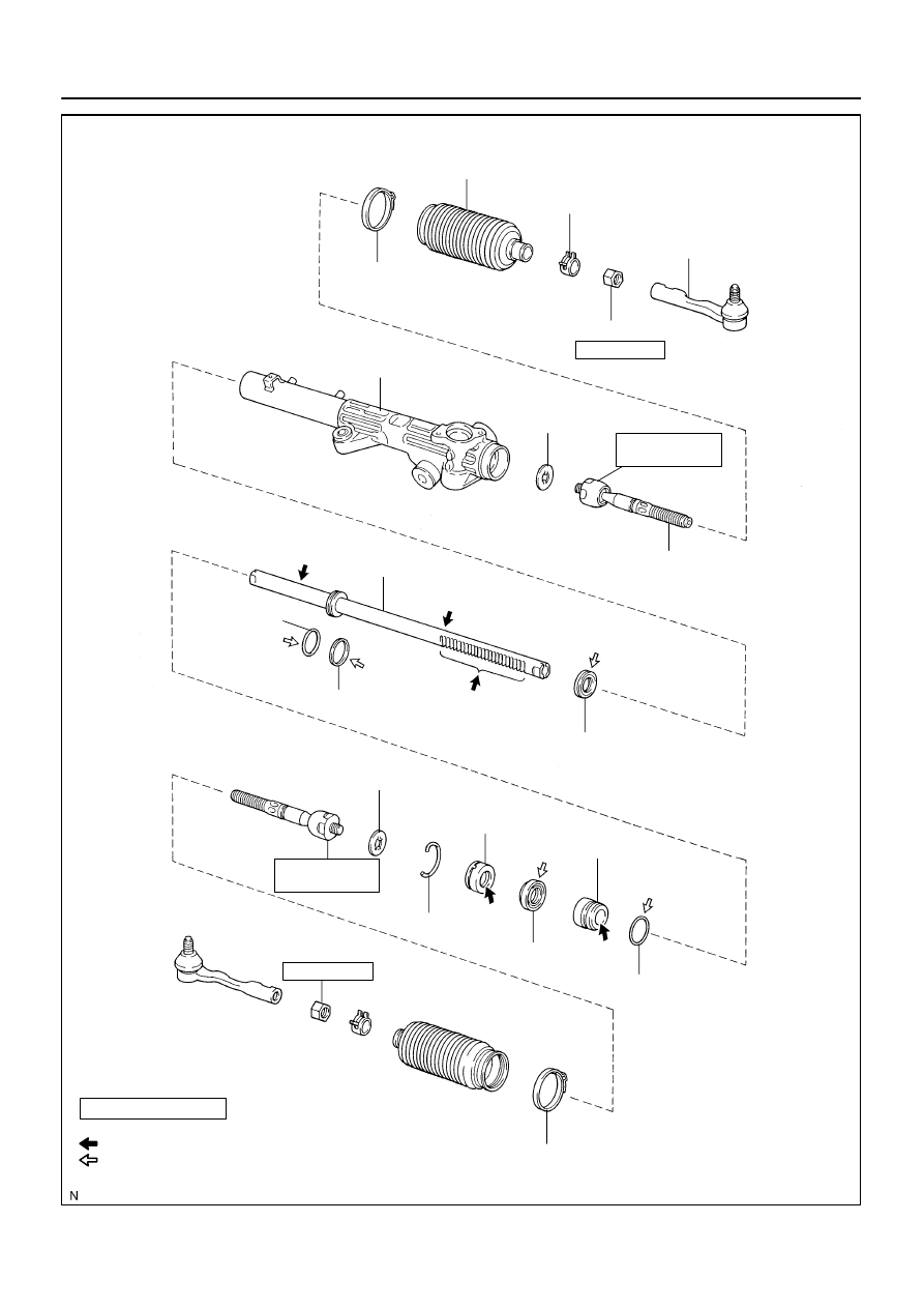
Rack Housing
Claw Washer
Rack End
Lock Nut
Tie Rod End
Rack Boot
Clamp
Clip
Steering Rack
Teflon Ring
Oil Seal
Bushing
O–Ring
Oil Seal
Wire
N·m (kgf·cm, ft·lbf) : Specified touque
Power steering fluid
For use with SST
Non–reusable part
Molybdenum disulfide lithium base grease
*
O–Ring
55 (560, 41)
103 (1,050, 76)
*76 (770, 56)
55 (560, 41)
103 (1,050, 76)
*76 (770, 56)
Cylinder End Stopper
SR–38
–
STEERING
POWER STEERING GEAR
3265
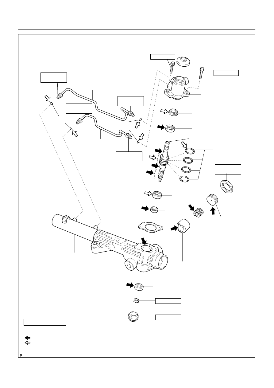
Rack Housing Cap
59 (600, 43)
F13619
Turn Pressure Tube
Dust Cover
Turn Pressure Tube
O–Ring
Control Valve
Housing
Oil Seal
Bearing
Teflon Ring
Rack Guide Spring
Rack Guide
Sub–assembly
Self–locking Nut
Bearing
N·m (kgf·cm, ft·lbf) : Specified torque
Non–reusable part
Precoated part
Molybdenum disulfide lithium base grease
Power steering fluid
For use with SST
Rack Housing
Bearing
Gasket
Control Valve Assembly
*
Oil seal
15 (150, 11)
*13 (135, 10)
18 (185, 13)
59 (600, 43)
*44 (450, 32)
Rack Guide
Spring Cap
25 (250, 18)
18 (185, 13)
15 (150, 11)
*13 (135, 10)
15 (150, 11)
*13 (135, 10)
15 (150, 11)
*13 (135, 10)
Rack Guide Spring
Cap Lock Nut
O–Ring
–
STEERING
POWER STEERING GEAR
SR–39
3266
SR02O–09
F13616
SST
SR–40
–
STEERING
POWER STEERING GEAR
3267
REMOVAL
NOTICE:
Remove the steering wheel assembly before the steering
gear removal, because there is possibility of breaking of
the spiral cable.
1.
DISCONNECT CABLE FROM NEGATIVE BATTERY
TERMINAL
Wait for 90 seconds after disconnecting the cable to prevent the
airbag working.
2.
PLACE FRONT WHEELS FACING STRAIGHT AHEAD
3.
REMOVE STEERING WHEEL PAD
(See page
4.
REMOVE STEERING WHEEL (See page
5.
DISCONNECT RH AND LH TIE ROD ENDS
(See page
6.
DISCONNECT NO. 2 INTERMEDIATE SHAFT AS-
SEMBLY (See page
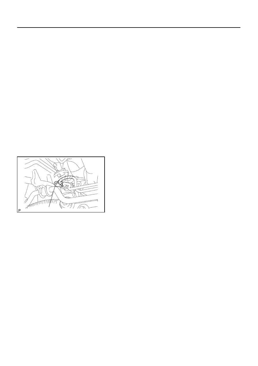
7.
DISCONNECT CLAMP PLATE
Remove the bolt and disconnect the clamp plate.
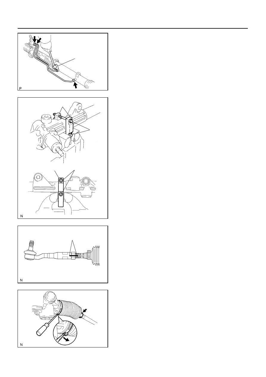
8.
DISCONNECT PRESSURE FEED AND RETURN
TUBES
Using SST, disconnect the tubes.
SST
09023–12701
9.
REMOVE PS GEAR ASSEMBLY
(a)
Remove the bolt, nut and stud bolt from the bracket.
(b)
Remove the 2 set bolts, nut, washer and PS gear assem-
bly.
10.
REMOVE BRACKET AND GROMMET
SR0V9–05
F13620
SST
F06746
SST
Bolt
SST
Nut
F06747
Matchmarks
F06748
–
STEERING
POWER STEERING GEAR
SR–41
3268
DISASSEMBLY
NOTICE:
When using a vise, do not overtighten it.
1.
REMOVE 2 TURN PRESSURE TUBES
(a)
Using SST, remove the 2 turn pressure tubes.
SST
09023–38401
(b)
Remove the 4 O–rings from the tubes.
2.
SECURE PS GEAR ASSEMBLY IN VISE
Using SST, 2 bolts and nuts, secure the gear assembly in a vise,
as shown in the illustration.
SST
09612–00012
Reference:
Bolt: 90105–10346
Nut: 90170–10198
HINT:
Use 2 of the same type of SST.
3.
REMOVE RH AND LH TIE ROD ENDS AND LOCK
NUTS
(a)
Put matchmarks on the tie rod end, lock nut and rack end.
(b)
Loosen the lock nut, remove the tie rod end and lock nut.
(c)
Perform the same procedure on the other side.
4.
REMOVE RH AND LH CLIPS, RACK BOOTS AND
CLAMPS
(a)
Using a screwdriver, loosen the 2 clamps.
(b)
Remove the 2 clips and boots.
HINT:
Mark the RH and LH boots.
NOTICE:
Be careful not to damage the boot.
Нет комментариевНе стесняйтесь поделиться с нами вашим ценным мнением.
Текст