Toyota Sequoia (2005). Manual — part 818
SR0V8–04
F04809
Inscribed Mark
F04810
Round End
F01507
SR–34
–
STEERING
POWER STEERING VANE PUMP
3261
REASSEMBLY
NOTICE:
When using a vise, do not overtighten it.
1.
COAT PARTS INDICATED BY ARROWS WITH POWER
STEERING FLUID (See page
)
2.
INSTALL VANE PUMP SHAFT WITH VANE PUMP
PULLEY
3.
INSTALL STRAIGHT PINS
Using a plastic hammer, tap in 2 new pins into the front housing.
NOTICE:
Be careful not to damage the pins.
4.
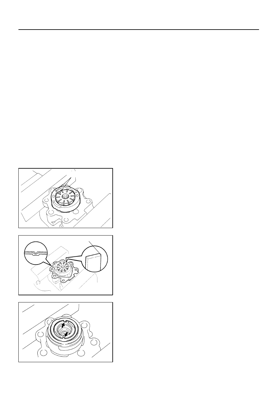
INSTALL CAM RING
Install the cam ring with the inscribed mark facing outward.
HINT:
Align the hole of the cam ring with the one of the straight pins.
5.
INSTALL VANE PUMP ROTOR
(a)
Install the vane pump rotor with the inscribed mark facing
outward.
(b)
Install a new snap ring to the vane pump shaft.
6.
INSTALL VANE PLATES AND GASKET
(a)
Install the 10 plates with the round end facing outward.
(b)
Install a new gasket on the front housing.
NOTICE:
Be careful of the direction of the gasket.
7.
INSTALL SIDE PLATE
Align the hole of the plate with the hole of the 2 straight pins.
8.
INSTALL WAVE WASHER
Install the washer so that the protrusions fit into the slots in the
side plate.
9.
INSTALL REAR HOUSING
(a)
Coat 2 new O–rings with power steering fluid and install
them to the rear housing.
(b)
Install the rear housing with the 4 bolts.
Torque: 24 N·m (240 kgf·cm, 17 ft·lbf)
–
STEERING
POWER STEERING VANE PUMP
SR–35
3262
10.
INSTALL SPRING, FLOW CONTROL VALVE AND
PRESSURE PORT UNION
(a)
Install the spring on the front housing.
(b)
Install the flow control valve in the correct direction
(See page
(c)
Coat a new O–ring with power steering fluid and install it
on the pressure port union.
(d)
Install the pressure port union.
Torque: 83 N·m (850 kgf·cm, 61 ft·lbf)
11.
INSTALL SUCTION PORT UNION
(a)
Coat a new O–ring with power steering fluid and install it
on the suction port union.
(b)
Install the suction port union with the bolt.
Torque: 13 N·m (130 kgf·cm, 9 ft·lbf)
12.
MEASURE PS VANE PUMP ROTATING TORQUE
(See page
SR0MI–14
F06724
Stopper
EM6656
SR–36
–
STEERING
POWER STEERING VANE PUMP
3263
INSTALLATION
1.
INSTALL PS VANE PUMP ASSEMBLY
(a)
Install the PS vane pump assembly with the stud bolt.
Torque: 22 N·m (220 kgf·cm, 16 ft·lbf)
(b)
Install the 2 bolt and nut.
Torque: 44 N·m (450 kgf·cm, 33 ft·lbf)
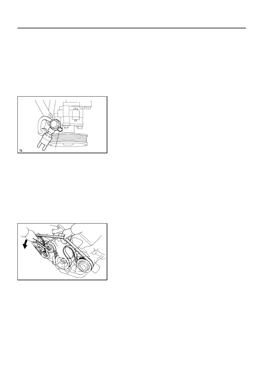
2.
INSTALL PRESSURE FEED TUBE
(a)
Connect the pressure feed tube.
(b)
Install a new gasket and the union bolt on the pressure
feed tube.
HINT:
Make sure that the stopper of the pressure feed tube contacts
the PS vane pump body as shown in the illustration, then tight-
en the union bolt.
Torque: 46.5 N·m (475 kgf·cm, 34 ft·lbf)
3.
CONNECT RETURN HOSE
Connect the return hose with the clip.
4.
CONNECT 2 VACUUM HOSES
Connect the 2 vacuum hoses and install the 2 clips.
5.
INSTALL DRIVE BELT
Loosen the drive belt tension by turning the drive belt tensioner
counterclockwise, and install the belt.
6.
INSTALL AIR CLEANER ASSEMBLY WITH AIR
CLEANER HOSE
(a)
Install the air cleaner assembly with air cleaner hose and
the 3 bolts.
(b)
Install the clamp.
(c)
Connect the hoses.
(d)
Connect the MAF meter connector.
7.
BLEED POWER STEERING SYSTEM
(See page
SR02N–08
F17905
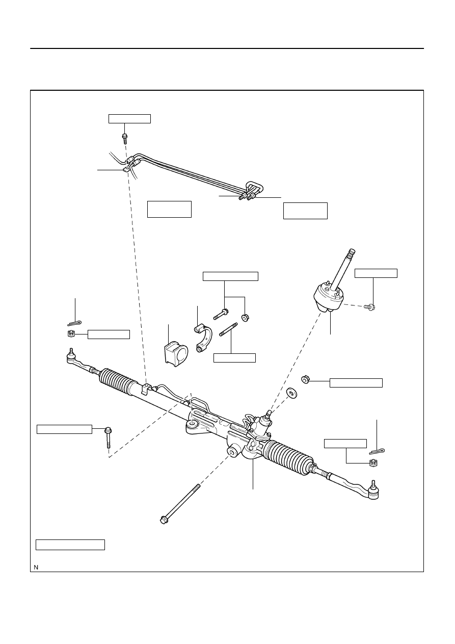
Bracket
Grommet
PS Gear Assembly
Pressure Feed Tube
: Specified torque
Non–reusable part
* For use with SST
N·m (kgf·cm, ft·lbf)
29 (290, 21)
Clamp Plate
Return Tube
25 (250, 18)
*22 (227, 16)
25 (250, 18)
*22 (227, 16)
Cotter Pin
91 (930, 67)
165 (1,700, 123)
35 (360, 26)
No. 2 Intermediate
Shaft Assembly
91 (930, 67)
165 (1,700, 123)
20 (200, 15)
130 (1,350, 96)
–
STEERING
POWER STEERING GEAR
SR–37
3264
POWER STEERING GEAR
COMPONENTS
Нет комментариевНе стесняйтесь поделиться с нами вашим ценным мнением.
Текст