Toyota Tundra. Manual — part 2714

Courtesy of TOYOTA MOTOR SALES, U.S.A., INC.
HINT:
Limit positions can be confirmed on the screen of the intelligent tester or Techstream.
DETECTION CONDITION AND TROUBLE AREA TABLE
WIRING DIAGRAM
Fig. 30: Identifying Telescopic Position Sensor Or Telescopic Motor Circuit Malfunction - Wiring
Diagram
Courtesy of TOYOTA MOTOR SALES, U.S.A., INC.
INSPECTION PROCEDURE
HINT:
The wire harness between the multiplex tilt and telescopic ECU and telescopic motor is provided with the
DTC
Code
Detection Condition
Trouble Area
B2611
Telescopic operation stops within the operation
range while operating.
Harness or connector
Telescopic position sensor or
telescopic motor
Multiplex tilt and telescopic ECU
2009 Toyota Tundra
2009 STEERING Steering Column - Tundra
steering column assembly.
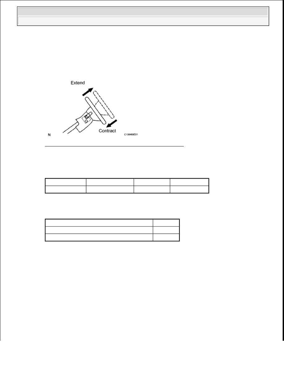
1. PERFORM ACTIVE TEST USING TECHSTREAM (TELESCO SHORT/LONG)
a. Select the Active Test, use the Techstream to generate a control command, and then check that the
steering column contracts and extends.
Fig. 31: Identifying Steering Column Contracts & Extends
Courtesy of TOYOTA MOTOR SALES, U.S.A., INC.
Tilt & Telescopic
TILT AND TELESCOPIC - ACTIVE TEST TABLE
Result
RESULT REFERENCE TABLE
B: Go to step 3
A: Go to next step.
2. CHECK TELESCOPIC MOTOR
a. Disconnect connector A from the multiplex tilt and telescopic ECU.
b. Apply 12 V battery voltage to the multiplex tilt and telescopic ECU connector. Then check the
steering wheel telescopic operation.
Tester Display
Test Part
Control Range Diagnostic Note
Telesco operation Telescopic operation LONG/SHORT
-
Result
Proceed to
The steering column does not contract (extend).
A
The steering column contracts (extends).
B
2009 Toyota Tundra
2009 STEERING Steering Column - Tundra

Fig. 32: Identifying Multiplex Tilt & Telescopic ECU Connector
Courtesy of TOYOTA MOTOR SALES, U.S.A., INC.
OK:
BATTERY VOLTAGE SPECIFICATION TABLE
NG: REPLACE STEERING COLUMN ASSEMBLY (See STEERING COLUMN ASSEMBLY
(for Power Tilt and Power Telescopic Steering Column) )
OK: REPLACE MULTIPLEX TILT AND TELESCOPIC ECU (See MULTIPLEX TILT AND
TELESCOPIC ECU (for Power Tilt and Power Telescopic Steering Column) )
3. CHECK MULTIPLEX TILT AND TELESCOPIC ECU (VCE TERMINAL VOLTAGE)
a. Measure the voltage according to the value (s) in the table below.
Standard Voltage
STANDARD VOLTAGE SPECIFICATION TABLE
Measurement Condition
Specified Condition
12 V battery positive (+) lead
--> Terminal A-2 (TEM+)
12 V battery negative (-) lead
--> Terminal A-6 (TEM-)
The steering column contracts.
12 V battery positive (+) lead
--> Terminal A-6 (TEM-)
12 V battery negative (-) lead
--> Terminal A-2 (TEM+)
The steering column extends
Tester Connection Switch Condition Specified Condition
A-3 (VCE) - A-5 (E2) Ignition switch ON
8 to 16 V
2009 Toyota Tundra
2009 STEERING Steering Column - Tundra

Fig. 33: Identifying Multiplex Tilt & Telescopic ECU Connector Terminal
Courtesy of TOYOTA MOTOR SALES, U.S.A., INC.
NG: Go to step 5
OK: Go to next step.
4. CHECK TELESCOPIC POSITION SENSOR
a. Measure the voltage according to the value (s) in the table below.
Standard Voltage
STANDARD VOLTAGE SPECIFICATION TABLE
Tester Connection
Condition
Specified Condition
A-4 (TES) - A-5 (E2) Telescopic steering contracted or extended
Pulse generation
High: 8 to 16 V
Low: Below 1 V
2009 Toyota Tundra
2009 STEERING Steering Column - Tundra
Нет комментариевНе стесняйтесь поделиться с нами вашим ценным мнением.
Текст