Toyota Tundra. Manual — part 2713

Fig. 25: Identifying J47 Multiplex Tilt & Telescopic ECU & J48 Tilt Motor Connectors
Courtesy of TOYOTA MOTOR SALES, U.S.A., INC.
c. Measure the resistance according to the value (s) in the table below.
Standard Resistance
STANDARD RESISTANCE SPECIFICATION TABLE
NG: REPAIR OR REPLACE HARNESS OR CONNECTOR
OK: Go to next step.
5. CHECK HARNESS AND CONNECTOR (MULTIPLEX TILT AND TELESCOPIC ECU - BODY
GROUND)
a. Measure the resistance according to the value (s) in the table below.
Standard Resistance
STANDARD RESISTANCE SPECIFICATION TABLE
Tester Connection
Condition Specified Condition
J47-6 (VCI) - J48-4 (VCI)
Always
Below 1 ohms
J47-7 (TIS) - J48-5 (TIS)
Always
Below 1 ohms
J47-17 (E1) - J48-6 (E1)
Always
Below 1 ohms
J47-6 (VCI) - Body ground Always
10 kohms or higher
J47-7 (TIS) - Body ground
Always
10 kohms or higher
J47-17 (E1) - Body ground Always
10 kohms or higher
Tester Connection
Condition Specified Condition
J47-11 (GND) - Body ground Always
Below 1 ohms
2009 Toyota Tundra
2009 STEERING Steering Column - Tundra
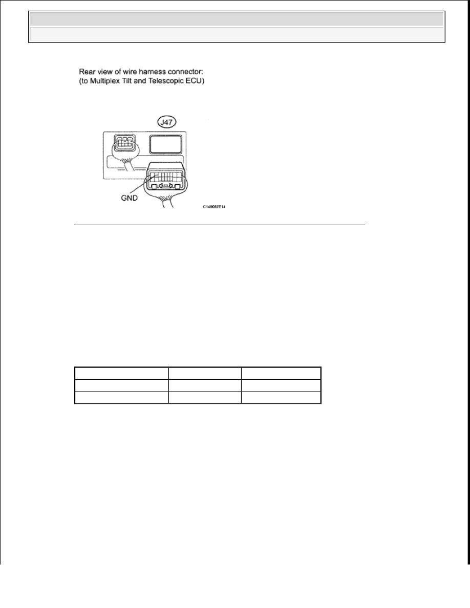
Fig. 26: Identifying Multiplex Tilt & Telescopic ECU Connector Terminal
Courtesy of TOYOTA MOTOR SALES, U.S.A., INC.
NG: REPAIR OR REPLACE HARNESS OR CONNECTOR
OK: Go to next step.
6. CHECK MULTIPLEX TILT AND TELESCOPIC ECU (VCI, TIS TERMINAL VOLTAGE)
a. Reconnect the J47 multiplex tilt and telescopic ECU connector.
b. Measure the voltage according to the value (s) in the table below.
Standard Voltage
STANDARD VOLTAGE SPECIFICATION TABLE
Tester Connection
Switch Condition Specified Condition
J48-4 (VCI) - J48-6 (E1) Ignition switch ON
8 to 16 V
J48-5 (TIS) - J48-6 (E1) Ignition switch ON
8 to 16 V
2009 Toyota Tundra
2009 STEERING Steering Column - Tundra

Fig. 27: Identifying J48 Tilt Motor Connector
Courtesy of TOYOTA MOTOR SALES, U.S.A., INC.
NG: REPLACE MULTIPLEX TILT AND TELESCOPIC ECU (See MULTIPLEX TILT AND
TELESCOPIC ECU (for Power Tilt and Power Telescopic Steering Column) )
OK: Go to next step.
7. CHECK TILT POSITION SENSOR
a. Reconnect the J48 tilt motor connector.
b. Measure the voltage according to the value (s) in the table below.
Standard Voltage
STANDARD VOLTAGE SPECIFICATION TABLE
Tester Connection
Condition
Specified Condition
J47-7 (TIS) - J47-17 (E1) Steering tilts up or tilts down
Pulse generation
High: 8 to 16 V
Low: Below 1 V
2009 Toyota Tundra
2009 STEERING Steering Column - Tundra

Fig. 28: Identifying J47 Multiplex Tilt & Telescopic ECU Connector
Courtesy of TOYOTA MOTOR SALES, U.S.A., INC.
NG: REPLACE STEERING COLUMN ASSEMBLY (See STEERING COLUMN ASSEMBLY
(for Power Tilt and Power Telescopic Steering Column) )
OK: REPLACE MULTIPLEX TILT AND TELESCOPIC ECU (See MULTIPLEX TILT AND
TELESCOPIC ECU (for Power Tilt and Power Telescopic Steering Column) )
DTC B2611: TELESCOPIC POSITION SENSOR OR TELESCOPIC MOTOR CIRCUIT
MALFUNCTION
DESCRIPTION
The telescopic motor is operated by the power source voltage supplied from the multiplex tilt and telescopic
ECU and slides the steering column forward and backward. The telescopic position sensor (Hall IC) in the
telescopic motor detects the sliding position in the forward and backward directions of the steering column and
outputs a signal to the multiplex tilt and telescopic ECU based on that sliding amount.
Fig. 29: Identifying Steering Column Forward & Backward Position
2009 Toyota Tundra
2009 STEERING Steering Column - Tundra
Нет комментариевНе стесняйтесь поделиться с нами вашим ценным мнением.
Текст