Toyota Tundra. Manual — part 1816
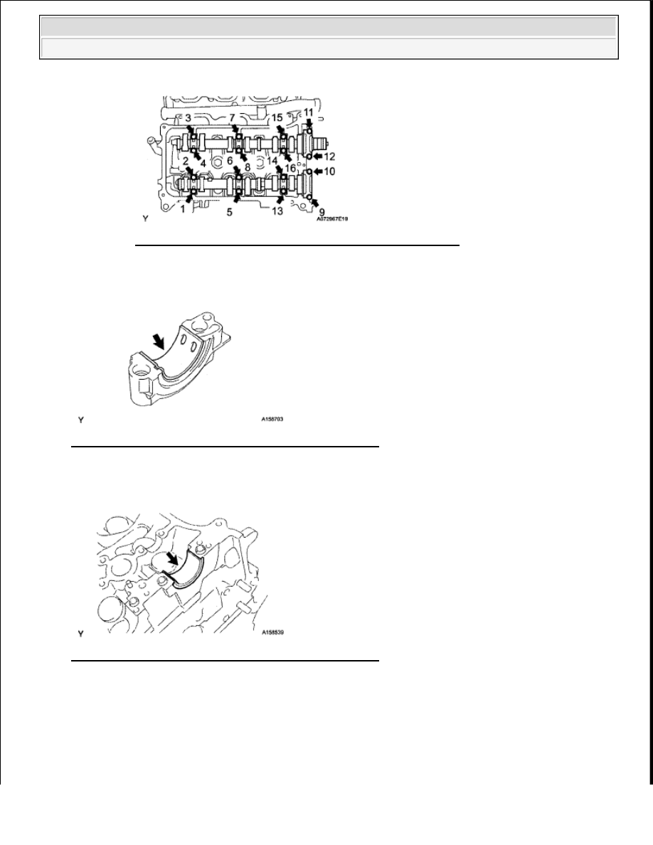
Fig. 270: Identifying Bearing Cap Bolt Loosening Sequence
Courtesy of TOYOTA MOTOR SALES, U.S.A., INC.
46
REMOVE NO. 1 CAMSHAFT BEARING (for Bank 1)
Fig. 271: Locating No. 1 Camshaft Bearing (For Bank 1)
Courtesy of TOYOTA MOTOR SALES, U.S.A., INC.
47
REMOVE NO. 2 CAMSHAFT BEARING (for Bank 1)
Fig. 272: Locating No. 2 Camshaft Bearing (For Bank 1)
Courtesy of TOYOTA MOTOR SALES, U.S.A., INC.
48
REMOVE NO. 3 CAMSHAFT AND NO. 4 CAMSHAFT (for Bank 2)
a
Remove the No 3 and No 4 camshafts
1
Uniformly loosen and remove the 16 bearing cap bolts in the sequence shown below
2
Remove the 8 bearing caps and 2 camshafts
2009 Toyota Tundra
2009 ENGINE Engine Mechanical (1GR-FE) - Tundra

Fig. 273: Identifying Bearing Cap Bolt Loosening Sequence
Courtesy of TOYOTA MOTOR SALES, U.S.A., INC.
49
REMOVE CYLINDER HEADS
a
Using a 10 mm bi-hexagon wrench, uniformly loosen the 2 bolts in the sequence shown below
Remove the 2 cylinder head bolts and plate washers
Fig. 274: Identifying Cylinder Head Bolt Loosening Sequence
Courtesy of TOYOTA MOTOR SALES, U.S.A., INC.
b
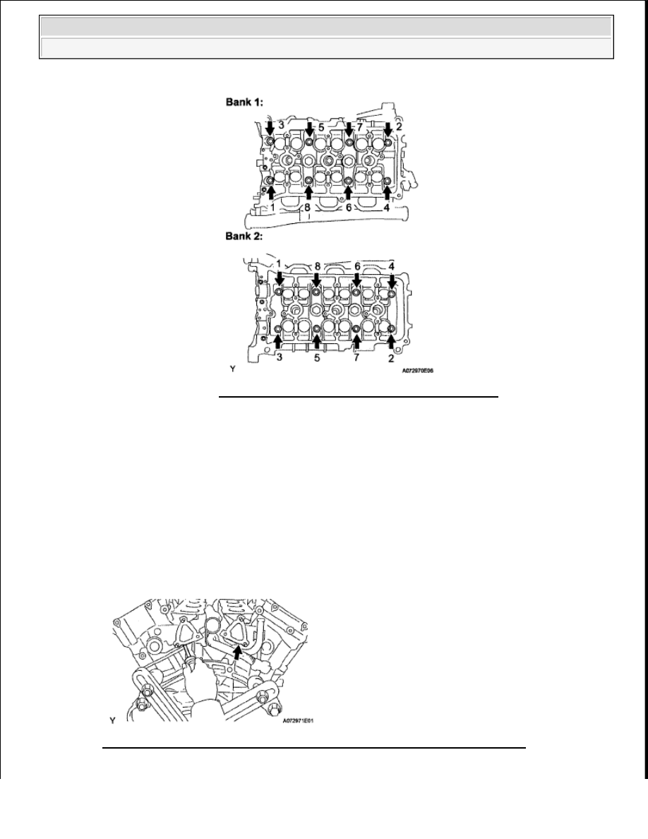
Using a 10 mm bi-hexagon wrench, uniformly loosen the 16 bolts in the sequence shown below
Remove the 16 cylinder head bolts and plate washers
NOTE:
Be careful not to drop the plate washers into the cylinder head.
Cylinder head warpage or cracking could result from removing
bolts in the incorrect order.
2009 Toyota Tundra
2009 ENGINE Engine Mechanical (1GR-FE) - Tundra
c
Lift the cylinder head from the dowels on the cylinder block, and place the 2 cylinder heads on
wooden blocks on a bench
HINT:
If the cylinder head is difficult to lift off, pry between the cylinder head and cylinder block with a
screwdriver
Fig. 276: Prying Between Cylinder Head & Cylinder Block Using Screwdriver
Courtesy of TOYOTA MOTOR SALES, U.S.A., INC.
Fig. 275: Identifying Bolt Loosening Sequence
Courtesy of TOYOTA MOTOR SALES, U.S.A., INC.
NOTE:
Be careful not to damage the contact surfaces of the cylinder head
and cylinder block.
2009 Toyota Tundra
2009 ENGINE Engine Mechanical (1GR-FE) - Tundra
50
REMOVE CYLINDER HEAD GASKET
51
REMOVE NO. 2 CYLINDER HEAD GASKET
52
REMOVE NO. 1 WATER OUTLET PIPE
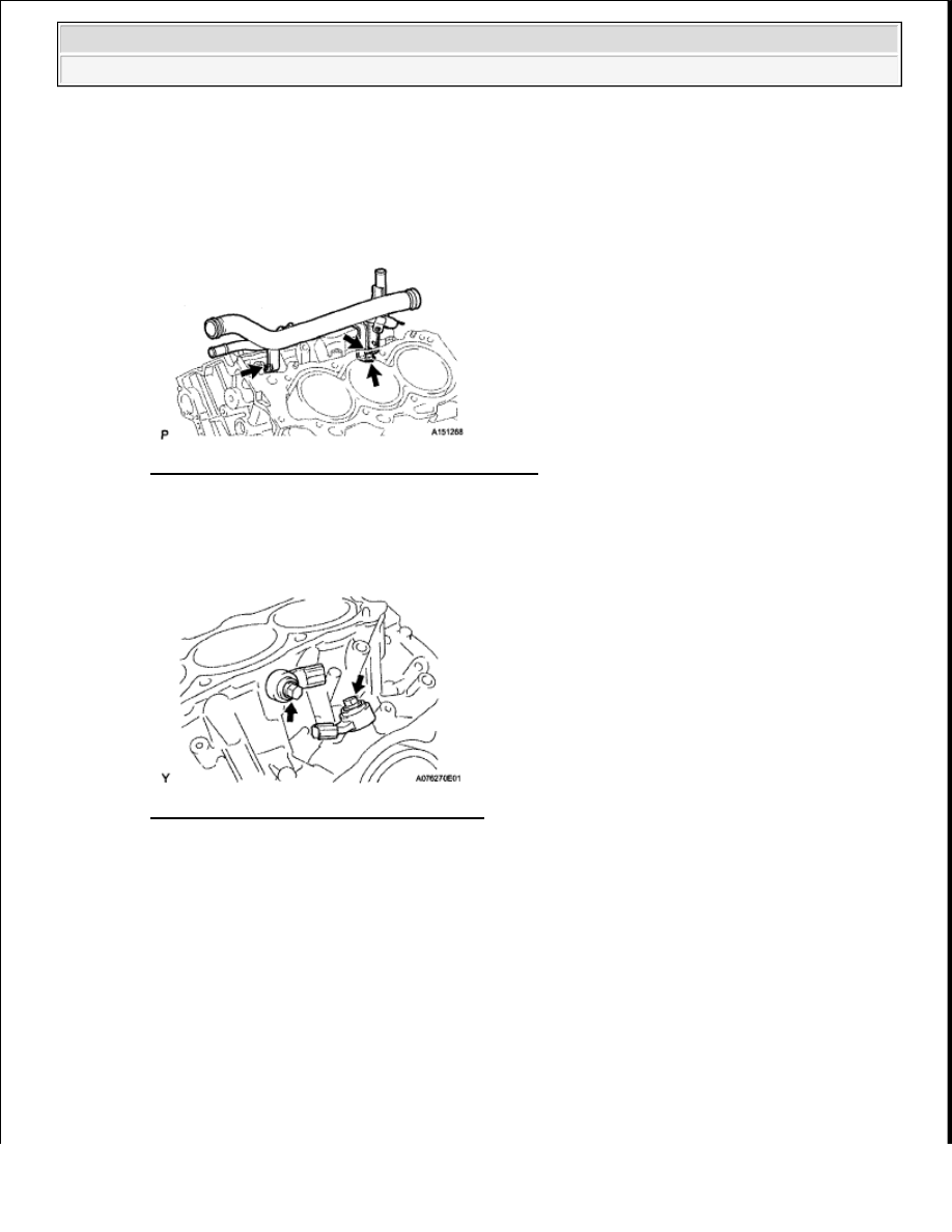
a
Remove the 3 bolts and water outlet pipe
Fig. 277: Locating No. 1 Water Outlet Pipe Bolts
Courtesy of TOYOTA MOTOR SALES, U.S.A., INC.
53
REMOVE KNOCK SENSOR
a
Remove the 2 bolts and 2 knock sensors
Fig. 278: Locating Knock Sensors & Bolts
Courtesy of TOYOTA MOTOR SALES, U.S.A., INC.
INSPECTION
1
INSPECT CYLINDER HEAD SET BOLT
a
Using a vernier caliper, measure the outside thread diameter of the bolt
Measuring point: 73.0 mm (2.87 in.)
Standard outside diameter: 10.85 to 11.0 mm (0.427 to 0.433 in.)
Minimum outside diameter: 10.7 mm (0.421 in.)
2009 Toyota Tundra
2009 ENGINE Engine Mechanical (1GR-FE) - Tundra
Нет комментариевНе стесняйтесь поделиться с нами вашим ценным мнением.
Текст