Kia Carnival (2007 year). Manual — part 310
Rescue mode is entered when some important CAN signal or hardware input are not available. Rescue mode is
entered when one of the following conditions is true:
IPM
a. Timeout on CAN signal InhibitSwSts, to detect loss of CAN connection with FAM.
b. Timeout on CAN signal StopLpErrorSts, to detect loss of CAN connection with RAM.
c. MF Light Switch information is invalid: when the signals coming from MF Light Switch are not coherent for more
than 2 s, CAN signal ParkTailHeadLpCtrl is sent with INVALID value and rescue mode is entered.
d. Front Wiper MF Switch information is invalid: when the signals coming from Front Wiper MF Switch are not
coherent for more than 2 s, CAN signal FWiperCtrl is sent with INVALID value and rescue mode is entered.
e. CAN is in Bus Off state
RAM
a. Timeout on CAN signal InhibitSwSts, to detect loss of CAN connection with FAM.
b. Timeout on CAN signal ParkTailHeadLpCtrl or FWiperCtrl, to detect loss of CAN connection with IPM.
c. ParkTailHeadLpCtrl = INVALID or unknown value
d. FWiperCtrl = INVALID or unknown value
e. CAN is in Bus Off state
FAM
a. Timeout on CAN signal StopLpErrorSts, to detect loss of CAN connection with RAM
b. Timeout on CAN signal ParkTailHeadLpCtrl or FWiperCtrl, to detect loss of CAN connection with IPM
c. ParkTailHeadLpCtrl = INVALID or unknown value
d. FWiperCtrl = INVALID or unknown value
e. CAN is in Bus Off state
For all CAN signals, timeout duration is 2.5 times signal periodicity.
2007 > 2.7L V6 GASOLINE >
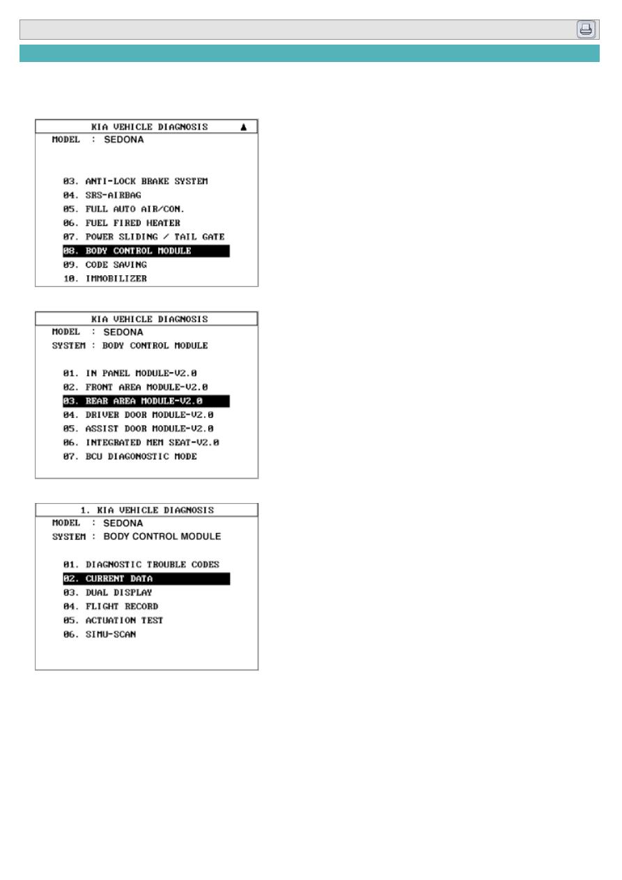
TROUBLE DIAGNOSTICS WHEN USING DIAGNOSIS TOOL
1. The diagnosis tool supports quick diagnosis of supported body electrical systems through input/output monitoring.
and actuation testing.
2. To diagnose the BCM function, select the menu of model and body control module.
3. Select the module menu to diagnose.
4. The CURRENT DATA function is used to monitor input/output conditions.
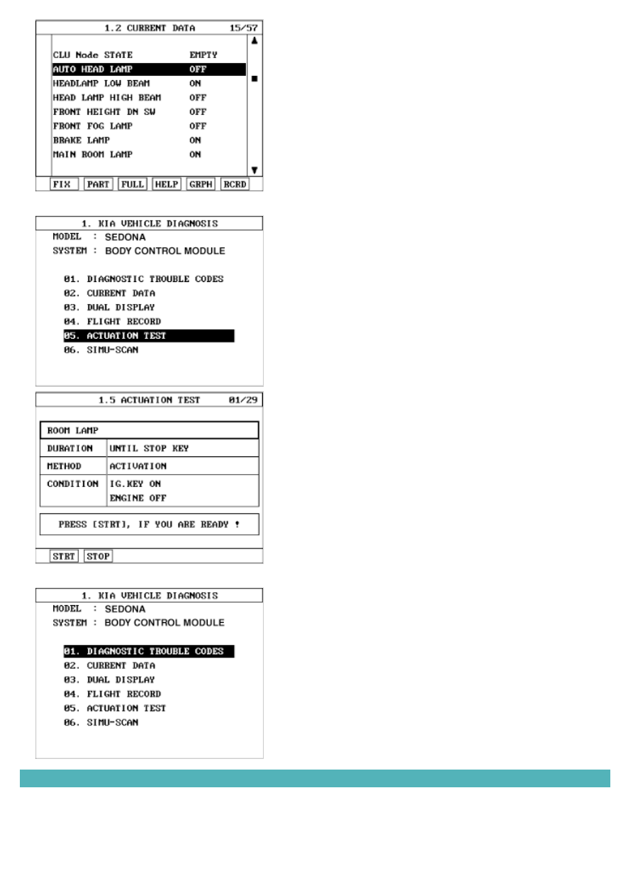
5. Use the ACTUATION TEST mode to force output devices to operate for testing purposes.
6. Use the "DIAGNOSTIC TROUBLE CODES" mode.
INSPECTION
1. The body network system consists of several ECUs that communicates via a CAN bus. The diagnostic tester is not
directly connected to the CAN bus, but utilises a one-wire communication line (K-line) that connects to a gateway
in the IPM ECU.
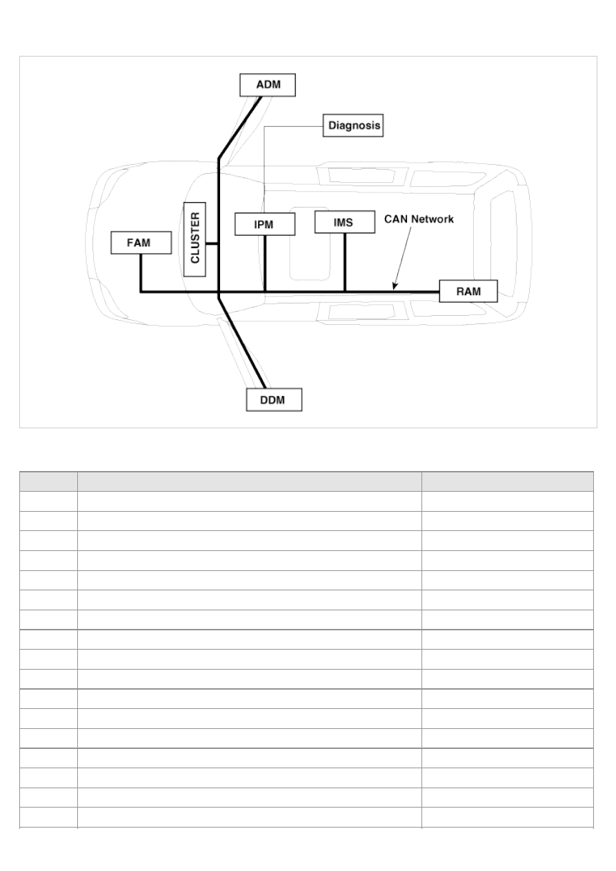
2. The IPM communicates with the diagnostic tester directly. But other units operate self diagnostic, input/output
monitoring and actuator operation via the IPM using the CAN communication.
INPUT MONITORING
IPM (In-Panel Module)
No.
Input switch
Unit
1
IPM Node Availability
PRESENT/NOT PRESENT
2
FAM Node Availability
PRESENT/NOT PRESENT
3
RAM Node Availability
PRESENT/NOT PRESENT
4
DDM Node Availability
PRESENT/NOT PRESENT
5
ADM Node Availability
PRESENT/NOT PRESENT
6
IMS Node Availability
PRESENT/NOT PRESENT
7
CLU Node Availability
PRESENT/NOT PRESENT
8
IPM Node Failure
FAILURE/ O.K
9
FAM Node Failurey
FAILURE/ O.K
10
RAM Node Failure
FAILURE/ O.K
11
DDM Node Failure
FAILURE/ O.K
12
ADM Node Failure
FAILURE/ O.K
13
IMS Node Failure
FAILURE/ O.K
14
CLU Node Failure
FAILURE/ O.K
15
Auto Head lamp
ON/OFF
16
Headlamp low beam
ON/OFF
17
High beam
ON/OFF
Нет комментариевНе стесняйтесь поделиться с нами вашим ценным мнением.
Текст