Kia Carnival (2007 year). Manual — part 309
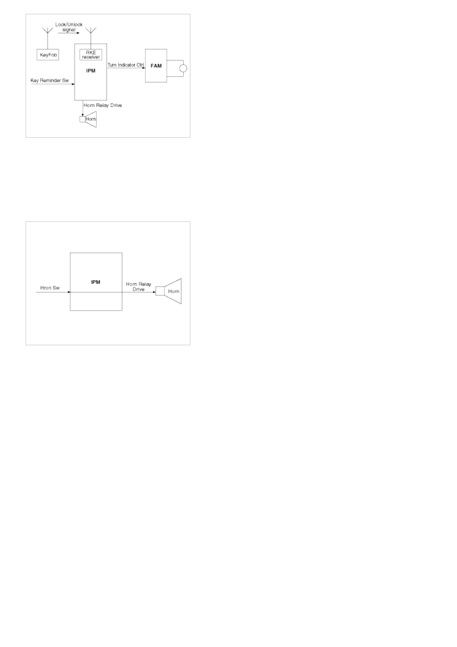
Horn
1. Working Conditions
Required key positions:
a. At any position of the key in the cylinder for the horn stalk activation,
b. At Key out from the key cylinder for the horn lock activation or for panic activation.
2. Functional Diagram
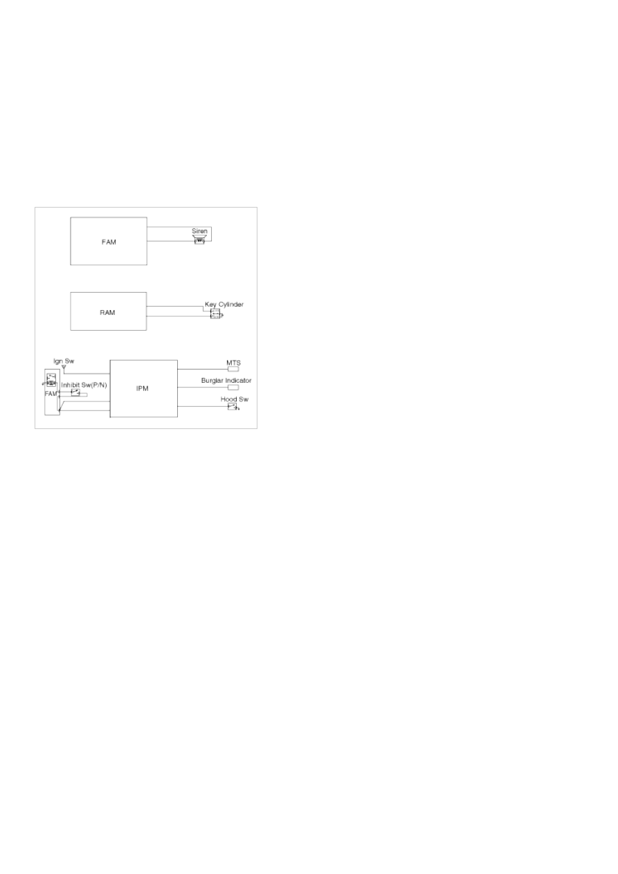
Burglar Alarm Function
Burglar Alarm
1. Basic Concept
a. The following functions are related to the RKE and burglar alarm systems..
a. Door locking
b. Door unlocking
c. PSD open/close (both for left and right)
d. PTG open/close
e. Panic
b. If IGN key is inserted into the key cylinder, the RKE transmitter functions are inoperative..
c. Door locking by RKE signal:
a. Whenever this signal is received, door LOCK pulse is always issued.
b. Hazard lamp flashes one time for 1 second depending on the burglar alarm state.
c. This signal will make the system possible to enter into the ARM state (or PREARM state depending on the
vehicle condition).
d. Door unlocking by RKE signal.
a. Whenever this signal is received, door UNLOCK pulse is always issued.
b. Hazard lamp flashes two times whenever the key fob unlock signal is received.
c. This signal will make the system possible to enter into the DISARM or 30sec DELAY state depending on
Condition A is true or not.
e. LH or RH PSD open/close by RKE signal.
a. Only with the information received by RKE, the burglar alarm system cannot distinguish the OPEN signal from
CLOSE signal.
CLOSE signal.
b. RAM will pass this signal to LH PSD and RH PSD then the burglar alarm state is decided depending on the
vehicle condition.
f. PTG open/close
a. Only with the information received by RKE, the burglar alarm system cannot distinguish the OPEN signal from
CLOSE signal.
b. RAM will pass this signal to PTG module then the burglar alarm state is decided depending on the vehicle
condition.
g. Panic by key fob
a. Whenever this signal is received, the PANIC function is activated (unless the system is already in an ALARM
state).
2. Functional Diagram
Arm Mode
a. If 30 second timer is elapsed without any changes from the ARM WAIT mode, then system goes to ARM mode.
b. Whenever RKE lock signal is received in the ARM state, then the system makes a hazard flash (1 second) and
sends a door lock pulse.
Prearm Mode
a. If the vehicle is locked using the RKE transmitter, and one or more doors are in an OPEN state, the system issues
a LOCK pulse and enters a PREARM state." In the PREARM state, the hazard lamps do not flash".
b. If all doors are closed in the PREARM state, the system enters ARM WAIT mode, and the hazard lamps will flash
once.
c. During PREMARM state, if f key reminder switch is ON & IGN 1 & IGN 2 are turned on in this state, the system
immediately goes to DISARM state
Arm Wait Mode
a. The ARM WAIT mode is active for 30 seconds. If any entrance (hood, doors, tailgate) is opened, any lock knob is
moved to an UNLOCK state, or the ignition switch is turned ON, the system will immediately enter DISARM mode.
The system will enter ARM state if none of the previously mention conditions occur during the 30-second ARM
WAIT mode.
T1 : 0.5 sec
T2 : 1.0 ± 0.1 sec
Disarm Mode
a. If RKE unlock signal is received, then UNLOCK output is issued together with the flashing of hazard lamp (two
times) and the system enters into the DISARM condition.
b. When entering into DISARM from ALARM state, current alarm will be cancelled and burglar alarm relay drive
output is turned off.
c. When RKE unlock signal is received again in the DISARM state, UNLOCK output is issued again and hazard lamp
is flashed also (two times).
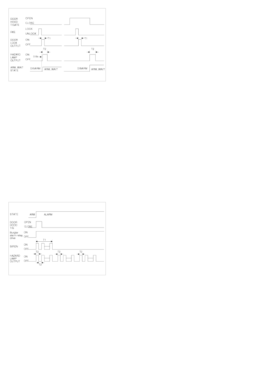
Alarm Mode
a. If one or more of entrances are opened in the ARM or REARM state, then Burglar alarm relay drive output is
turned ON in order to inhibit the start condition, and hazard lamp and siren are activated for once of 27 seconds
duration.
b. Siren output and hazard lamp should be synchronized to get the same output period.
c. Even though all the doors are closed during alarm, alarm continues to operate it for the remaining time.
d. When there is a new attack (with one of the entrance is still open) in the vehicle after completing the alarm output,
alarm should not be started again.
T1 : 27 sec (-0, +3sec)
T2 : 0.5 ± 0.1 sec
After Alarm State
a. If ALARM cycle is elapsed, the system goes into AFTER ALARM state.
b. During this state,
a. Burglar alarm relay drive output maintains ON.
b. Siren and hazard lamp output are stopped.
c. If another entry is opened during the AFTER ALARM state, the burglar alarm relay drive output remains ON, but
the siren will not be re-activated.
Rearm State
a. If all entrances are is closed during AFTER ALARM state, the system goes into REARM state.
Battery Removal
a. If the battery is removed with the system in the ARM state, the system will be placed into the ARM state upon
battery reconnect.
b. The ALARM state will be re-activated if the battery is disconnected, then reconnected, with the system in an
ALARM state.
c. If the battery is disconnected and reconnected with the system in AFTER ALARM state, the alarm will be re-
activated.
d. The system will enter DISARM mode if the battery is disconnected during the ALARM WAIT state.
Panic
a. If RKE PANIC signal is received, Siren output and hazard lamp operate for 27 seconds and the system return to
the previous state as soon as the PANIC function finishes.
b. The PANIC function will be stopped if any RKE signal is received during PANIC activation..
c. If Key reminder switch is ON during PANIC function is operating, PANIC is stopped immediately.
d. If the system goes to ALARM mode during PANIC function is operating, PANIC is stopped immediately and then
ALARM function should be activated.
e. During ALARM state;
If RKE PANIC signal is received, ALARM mode is maintained and PANIC function should be ignored. ALARM has
higher priority than PANIC function.
f. During AFTER_ALARM state;
If RKE PANIC signal is received, AFTR_ALARM mode is maintained and PANIC function should be activated.
Safe & Rescue Mode
The goal of those modes is to be able to cope with failures that may happen on some of the most critical
functionalities (for the driver security) of the system.
Safe Mode
The safe mode is entered in case of system problems such as:
a. Incoherent inputs on monitored signals. In this case, safe mode is the debouncing time before the inputs are
considered INVALID. Note that today, we have no way to detect if the rain/light sensor is in working operation or
not. It means that a driver action will be required in case of failure of this sensor;
b. Loss of the CAN frame containing the monitored signal:
c. Loss of the CAN network: CAN goes to BUS OFF state, safe mode is the time necessary for detecting the BUS
OFF state.
In all cases, the action in safe mode is to maintain the previous state of the system (for lighting and wiping). The list of
monitored signals is the same as in rescue mode
Exiting Safe Mode
The software safe mode is exited and the module goes back to the normal mode when:
a. On IPM, hardware inputs return to a coherent state;
b. The lost CAN signal comes back while timeout has not elapsed;
c. The CAN network returns to a normal state without reaching BUS OFF state.
Software safe mode is also exited when the software rescue mode is entered (problem does not disappear).
Hardware safe mode is exited and the module goes back to normal mode if the internal problem disappears (watchdog
is properly triggered again). If the problem stays, hardware safe mode is exited to enter hardware rescue mode.
Rescue Modes
The rescue mode consists in activating some safety functions when IGN2 = ON:
a. Switch on the low beams (FAM), park lamps (FAM), tail lamps (RAM) and cluster backlighting (IPM);
b. Unlock of all the doors when the rescue mode is entered with IGN2 = ON
c. Front wipers do not need to be turned on by software in rescue mode because wipers can be turned on by
manually setting the MF switch to low speed. The FAM software must keep the same state as before entering the
rescue mode.
d. When IGN2 = OFF, low beams, park/tail lamps and cluster backlighting are turned off.
Entering Rescue Modes
Нет комментариевНе стесняйтесь поделиться с нами вашим ценным мнением.
Текст